
Installation Manual
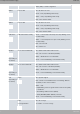
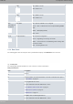
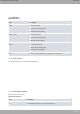
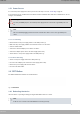
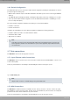
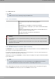
Table Of Contents
- Table of Contents
- I Related Documents
- 1 About This Guide
- 2 M8-Smart
- 3 Components and Power Supply
- 4 Compliance
- 4.1 Manufacturer Information
- 4.2 Risk identification
- 4.3 Safety Warnings
- 4.4 WEEE Information
- 4.5 REACH
- 4.6 Power Usage and Energy Efficiency
- 4.7 EC Declaration of Conformity (No Radio version)
- 4.8 EC Declaration of Conformity (Radio version)
- 4.9 CE Marking
- 4.10 National Restrictions
- 4.11 FCC Statements
- 4.12 Operating Frequency
- 4.13 Intended use of the equipment
- A Technical Information
- A.1 Troubleshooting
- A.2 Updating the software
- A.3 Connecting to the device
- A.4 Connectors
- A.5 Technical Specifications
- A.5.1 Hardware Architecture
- A.5.2 LAN Interface
- A.5.3 WAN Base-T Interface
- A.5.4 WAN SFP Interface
- A.5.5 Wireless WAN interface
- A.5.6 GPS interface
- A.5.7 Wireless LAN Interface (Radio 1)
- A.5.8 Wireless LAN Interface (Radio 2)
- A.5.9 Configuration Interface
- A.5.10 Power Supply
- A.5.11 Dimensions and weight
- A.5.12 Environmental Specifications
- B CE Radio Information
- C FCC Radio Information

O Cell connectors. Depending on the model.
For more information about Cellular interface, refer to:
- WWAN Antenna Connection (Cell connector) on page 15
- WWAN Connector on page 29
- Wireless WAN interface on page 33
P GPS connector. Depending on the model.
For more information about the GPS interface, refer to:
- Connecting the GPS antenna on page 17
- GPS Connector on page 30
- GPS interface on page 33
In addition to the foregoing, the rear panel also has LEDs linked to the Switch Ethernet interfaces.
3.1.2.1 LEDs
The following figure shows the router's Ethernet switch LED indicators:
Fig. 17: Switch LEDs
Switch LED indicators
LED Description
Yellow Connected to 10 M:
- Steady: Not transferring data.
- Blinking: Transferring data.
Yellow + Green Connected to 100 M:
- Steady: Not transferring data.
- Blinking: Transferring data.
Green Connected to 1000 M:
- Steady: Not transferring data.
- Blinking: Transferring data.
None The interface is either unavailable, not installed or not registered.
The following figure shows the router's WAN LED indicators, only for the Base-T connector:
Teldat S.A.
3 Components and Power Supply
M8-Smart 9