
Installation Manual
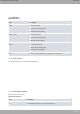
Table Of Contents
- Table of Contents
- I Related Documents
- 1 About This Guide
- 2 M8-Smart
- 3 Components and Power Supply
- 4 Compliance
- 4.1 Manufacturer Information
- 4.2 Risk identification
- 4.3 Safety Warnings
- 4.4 WEEE Information
- 4.5 REACH
- 4.6 Power Usage and Energy Efficiency
- 4.7 EC Declaration of Conformity (No Radio version)
- 4.8 EC Declaration of Conformity (Radio version)
- 4.9 CE Marking
- 4.10 National Restrictions
- 4.11 FCC Statements
- 4.12 Operating Frequency
- 4.13 Intended use of the equipment
- A Technical Information
- A.1 Troubleshooting
- A.2 Updating the software
- A.3 Connecting to the device
- A.4 Connectors
- A.5 Technical Specifications
- A.5.1 Hardware Architecture
- A.5.2 LAN Interface
- A.5.3 WAN Base-T Interface
- A.5.4 WAN SFP Interface
- A.5.5 Wireless WAN interface
- A.5.6 GPS interface
- A.5.7 Wireless LAN Interface (Radio 1)
- A.5.8 Wireless LAN Interface (Radio 2)
- A.5.9 Configuration Interface
- A.5.10 Power Supply
- A.5.11 Dimensions and weight
- A.5.12 Environmental Specifications
- B CE Radio Information
- C FCC Radio Information

- WAN Connections on page 14
- WAN Base-T Connector on page 29
- WAN Base-T Interface on page 31
E Eth WAN-1 SFP.
For more information about the SFP interface, refer to:
- WAN Connections on page 14
- WAN SFP Connector on page 29
- WAN SFP Interface on page 31
F Eth WAN-2 Base-T. WAN Gigabit Ethernet.
For more information about the WAN interface, refer to:
- WAN Connections on page 14
- WAN Base-T Connector on page 29
- WAN Base-T Interface on page 31
G Eth WAN-2 SFP.
For more information about the SFP interface, refer to:
- WAN Connections on page 14
- WAN SFP Connector on page 29
- WAN SFP Interface on page 31
H Aux. Provides access to the M8-Smart local console for configuration and monit-
oring purposes.
For more information about the Aux connector, refer to:
- Connecting for Configuration on page 17
- Configuration Connector on page 30
- Configuration Interface on page 35
I SIM Card 1-2. Slot where you can insert the SIM cards for the G modules.
Refer to Installing the SIM card on page 18 for more information about SIM install-
ation.
J On/Off switch.
K Power source connection (PSU).
Refer to Power Source on page 12 for more information about Power connection
and Power Supply on page 35 for power specifications applicable to theM8-Smart
device.
L LED S (Status). Refer to LEDs on page 5 for more information.
M LED PWR (Power). Refer to LEDs on page 5 for more information.
N Functional earthing. Usually disconnected.
3 Components and Power Supply Teldat S.A.
8 M8-Smart