
Installation Manual
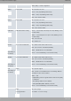
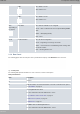
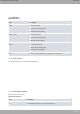
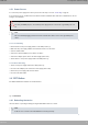
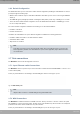
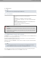
Table Of Contents
- Table of Contents
- I Related Documents
- 1 About This Guide
- 2 M8-Smart
- 3 Components and Power Supply
- 4 Compliance
- 4.1 Manufacturer Information
- 4.2 Risk identification
- 4.3 Safety Warnings
- 4.4 WEEE Information
- 4.5 REACH
- 4.6 Power Usage and Energy Efficiency
- 4.7 EC Declaration of Conformity (No Radio version)
- 4.8 EC Declaration of Conformity (Radio version)
- 4.9 CE Marking
- 4.10 National Restrictions
- 4.11 FCC Statements
- 4.12 Operating Frequency
- 4.13 Intended use of the equipment
- A Technical Information
- A.1 Troubleshooting
- A.2 Updating the software
- A.3 Connecting to the device
- A.4 Connectors
- A.5 Technical Specifications
- A.5.1 Hardware Architecture
- A.5.2 LAN Interface
- A.5.3 WAN Base-T Interface
- A.5.4 WAN SFP Interface
- A.5.5 Wireless WAN interface
- A.5.6 GPS interface
- A.5.7 Wireless LAN Interface (Radio 1)
- A.5.8 Wireless LAN Interface (Radio 2)
- A.5.9 Configuration Interface
- A.5.10 Power Supply
- A.5.11 Dimensions and weight
- A.5.12 Environmental Specifications
- B CE Radio Information
- C FCC Radio Information

SIM-1 Off -> SIM-1 not used.
ON -> SIM-1 in use.
SIM-2 Off -> SIM-2 not used.
ON -> SIM-2 in use.
GPS
(Depending on
the model)
GPS Status Off -> GPS not available or not configured.
Green -> GPS coordinates have been acquired. Blinking: NMEA
data.
Amber -> Bad quality (HDOP).
Red -> Error.
Cloud Cloud Information Off -> No Cloud configuration.
Green -> Registering /connecting to the Cloud.
Amber -> Connected to the Cloud. Blinking: traffic exchange with
the Cloud controller.
Red -> Cloud registration error.
3.1.2 Rear Panel
The following figure shows the rear panel. Here you will find the majority of the M8-Smart router connectors.
Fig. 16: Rear panel
The following table provides information on each connector, as well as a description:
Rear panel elements
Item Description
A
Function.
B RST. Reset button. For further information on how the reset button works, please
see RST Button on page 13.
C 4-port Gigabit Ethernet switch.
For more information about the LAN interface, refer to:
- 4-port Ethernet switch Connections on page 14
- LAN Connector (Switch) on page 29
- LAN Interface on page 31
D Eth WAN-1 Base-T. WAN Gigabit Ethernet.
For more information about the WAN interface, refer to:
Teldat S.A.
3 Components and Power Supply
M8-Smart 7