
User manual


TCPA300 and TCPA400 Performance Verification
5-10
TCPA300/400 Amplifiers and TCP300/400 Series Current Probes Instruction Manual
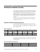
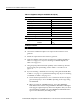
Table 5- 6: Equipment settings for bandwidth check (Cont.)
Oscilloscope
Record length 500
Coupling DC
Offset 0 V (mid-scale)
Trigger type Edge
Trigger mode Auto
Trigger position 50%
Acquisition mode Average
Number of waveforms to average 16
Measurement type Peak-to-Peak
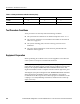
Leveled sine wave generator
Frequency 3MHz
Amplitude TCPA300
TCPA400
~3.0 V
p-p
1.0 V
p-p
TCPA300 and TCPA400
Coupling DC
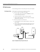
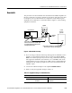
4. Connect the Calibration Adapter to the output of the leveled sine wave
generator.
5. Enable the output of the leveled sinewave generator.
6. Verify the amplifier output is what is listed for the TCPA300 amplifier in
Table 5--7 on page 5--11. If you are checking a TCPA400 amplifier, use
Table5--8onpage5--11.
7. Using the peak-peak measurement capability of the oscilloscope, measure
and record the peak-peak reading as M
1
in Table 5--7 or Table 5--8 on
page 5--11.
8. If you are checking a TCPA300, for each range setting and bandwidth filter
in Table 5--7 on page 5--11, perform the following steps. If you are checking
a TCPA400, use Table 5--8 on page 5--11.
a. Set the oscilloscope time base to 4 or 5 ns/division. Increase the signal
generator frequency to 50 or 100 MHz, depending on the range setting
and bandwidth.
b. When you check the 100 MHz frequency, press either MANUAL
BALANCE button until the orange MANUAL BALANCE LED lights.
This engages a higher -frequency filter in the amplifier. After you check
the bandwidth at 100 MHz, press either MANUAL BALANCE button
again to turn off the filter (the LED goes off.)