
User Manual

Setting channel
input parameters
Setting chann
el input parameters
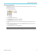
Use the vertical Menu buttons to select waveforms to d isplay or open menus and submenus with which to set input
parameters for each channel.
Each channel’s settings are independent of every other channel.
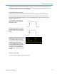
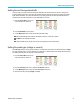
Setting input signal coupling
Input signal coupling sets how the input signal is pas sed to the oscilloscope sampling circuit.
1. Push the Ver
tical Menu button for the
channel input that you want to set.
2. Push the Coupling side-menu button.
3. Use the Multipurpose knob to select and click the coupling type:
DC coupling passes both AC and DC signal components.
AC coup
ling blocks the DC component and passes only the AC signal.
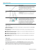
Ground internally disconnects the input signal and connects that channel to a ground reference. This is a fast way to
determ
ine where the ground level is for signals that have a DC component or offset.
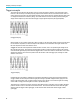
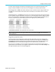
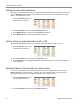
Inver
ting the input signal
Use this procedure to invert (flip vertically) the signal. A typical reason to invert a signal is to use the inverted signal to
create a math waveform.
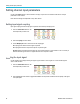
1. Push the Vertical Menu button for the
channel input that you want to set.
2. Push the Invert side-menu button to toggle between Off for normal operation and On to invert the polarity of the signal
in the preamplifier.
30 TBS2000 Series User Manual