
User Manual
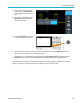


The graphical us
er interface elements
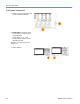
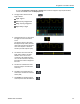
The trigger Del
ay Mode readout is
the time from the T symbol to the
expansion point icon (adjust with the
Horizontal Po
sition knob).
Use horizontal position to add delay
between when the trigger occurs and
when you actu
ally capture the data.
Insert a negative time to capture
more waveform data before the
trigger even
t.
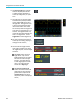
When Delay Mode is off, this readout
shows the time location of the trigger
within the w
aveform record, as a
percentage.
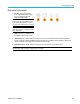
The Record
Length readout shows
how many samples are being stored
for the current waveform records.
(See page 4
4
,
Setting the record
length.)
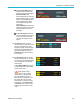
12. The channel readouts shows the
channel s
cale factor (measurement units
per major vertical graticule division),
input signal coupling, signal invert status,
and the o
scilloscope bandwidth setting.
Adjust these settings by using the
Vertical Scale knob and the channel 1,
2, 3,or
4 menus.
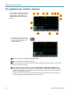
13. The measurement readouts show the
select
ed measurements. You can select
up to six measurements to display at one
time. (See page 50, Taking automatic
measu
rements.)
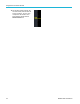
Push the Menu On /Off button to toggle
on off the display of the measurement
reado
uts on the screen.
A sym
bol appears next to a
measurement if a vertical clipping
condition exists. Clipping is when
part
of the waveform is above or
below the display. Clipping can cause
the oscilloscope to take inaccurate
mea
surements. To obtain an accurate
measurement, use the Vertical Scale
and Position knobs to show all of the
ver
tical range of the waveform on the
screen.
TBS2000 Series User Manual 109