User manual
Table Of Contents
- toc
- General safety summary
- Compliance Information
- Preface
- Getting Started
- Operating Basics
- Understanding Oscilloscope Functions
- Application Examples
- Taking Simple Measurements
- Using Autorange to Examine a Series of Test Points
- Taking Cursor Measurements
- Analyzing Signal Detail
- Capturing a Single-Shot Signal
- Measuring Propagation Delay
- Triggering on a Specific Pulse Width
- Triggering on a Video Signal
- Analyzing a Differential Communication Signal
- Viewing Impedance Changes in a Network
- Data Logging
- Limit Testing
- Math FFT
- USB Flash Drive and Device Ports
- USB Flash Drive Port
- File Management Conventions
- Saving and Recalling Files With a USB Flash Drive
- Using the Save Function of the Print Front Panel Button
- USB Device Port
- Installing the PC Communications Software on a PC
- Connecting to a PC
- Connecting to a GPIB System
- Command Entry
- Connecting to a Printer
- Printing a Screen Image
- Reference
- Appendix A: Specifications
- Appendix B: TPP0101 and TPP0201 Series 10X Passive Probes Inform
- Appendix C: Accessories
- Appendix D: Cleaning
- Appendix E: Default Setup
- Appendix F: Font Licenses

USB Flash Drive and Device Ports
This chapter describes how t o use the Universal Serial Bus (USB) ports on the
oscilloscope to do the following tasks:
Save and recall waveform data or setup data, or save a screen image
Print a screen image
Transfer waveform data, setup data, or a screen image to a PC
Control the oscilloscope with remote commands
To use the PC Communications software, launch and refer to the online help
from the software.
USB Flash Drive Port
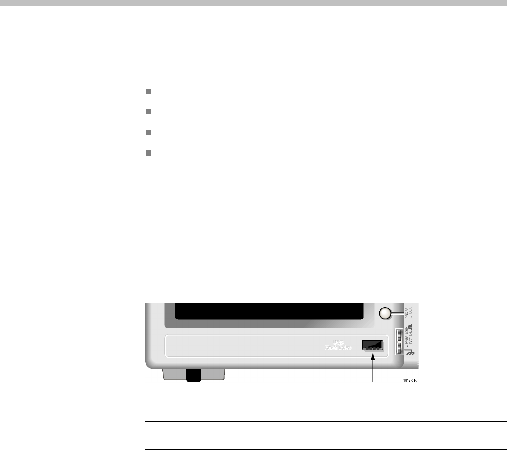
The front of
theoscilloscopehasaUSBFlashDriveporttoaccommodateaUSB
flash drive for file storage. The oscilloscope can save data to and retrieve data
from the flash drive.
USB F lash Drive port
NOTE. The oscilloscope can only support flash drives with a storage capacity
of 64 GB or less.
To c onnect a USB flas h drive, follow these steps:
1. Align the USB fl ash drive with the USB Flash Drive port on the oscilloscope.
Flash drives are shaped for proper installation.
2. Insert the flash drive into the port until the drive is fully inserted.
For flash drives with an LED, the drive "blinks" while the oscilloscope writes
data to or reads data from the drive. The oscilloscope also displays a clock
symbol to indicate when the flash drive is active.
After a file is saved or retrieved, the LED on the drive (if any) stops blinking,
and the oscilloscope removes the clock. A hint line also displays to notify you
that the sa ve or recall operation is complete.
TBS1000 Series Oscilloscopes User Manual 63


