User manual
Table Of Contents
- toc
- General safety summary
- Compliance Information
- Preface
- Getting Started
- Operating Basics
- Understanding Oscilloscope Functions
- Application Examples
- Taking Simple Measurements
- Using Autorange to Examine a Series of Test Points
- Taking Cursor Measurements
- Analyzing Signal Detail
- Capturing a Single-Shot Signal
- Measuring Propagation Delay
- Triggering on a Specific Pulse Width
- Triggering on a Video Signal
- Analyzing a Differential Communication Signal
- Viewing Impedance Changes in a Network
- Data Logging
- Limit Testing
- Math FFT
- USB Flash Drive and Device Ports
- USB Flash Drive Port
- File Management Conventions
- Saving and Recalling Files With a USB Flash Drive
- Using the Save Function of the Print Front Panel Button
- USB Device Port
- Installing the PC Communications Software on a PC
- Connecting to a PC
- Connecting to a GPIB System
- Command Entry
- Connecting to a Printer
- Printing a Screen Image
- Reference
- Appendix A: Specifications
- Appendix B: TPP0101 and TPP0201 Series 10X Passive Probes Inform
- Appendix C: Accessories
- Appendix D: Cleaning
- Appendix E: Default Setup
- Appendix F: Font Licenses

Application Examples
Measuring P ropagation Delay
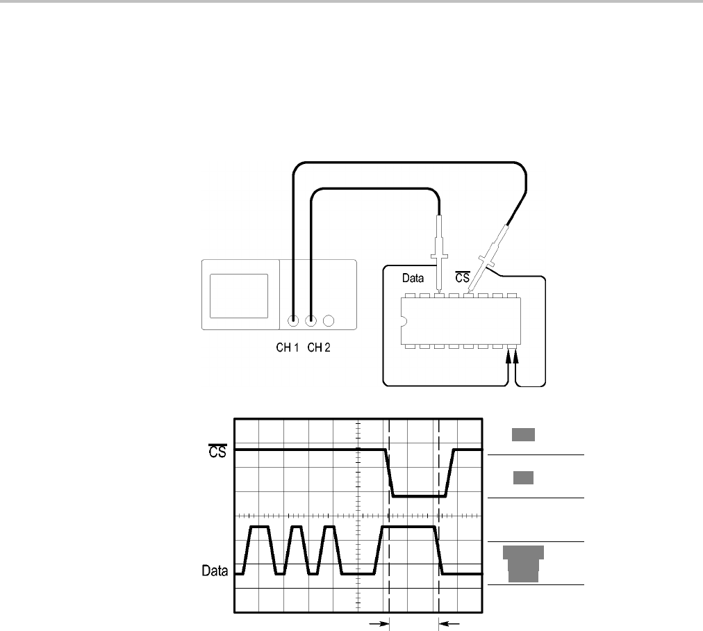
You suspect that the memory timing in a microprocessor circuit is marginal. Set
up the oscilloscope to measure the propagation delay between the chip-select
signal and the data output of the memory device.
Type
Time
Source
CH1
Δt 20.00ns
1/Δt50.00MHz
ΔV 0.28V
Cursor 1
50.0ns
-0.20V
Cursor 2
70.0ns
0.08V
To set up to measure propagation delay, follow these steps:
1. Push the AutoSet button to trigger a stable display.
2. Adjust the horizontal and vertical controls to optimize the display.
3. Push the Cursor button to see the Cursor Menu.
4. Push Type ► Time.
5. Push Source ► CH1.
6. Push the Cursor 1 option button.
7. Turn the multipurpose knob to place a cursor on the active edge of the
chip-select signal.
TBS1000 Series Oscilloscopes User Manual 43


