User manual
Table Of Contents
- toc
- General safety summary
- Compliance Information
- Preface
- Getting Started
- Operating Basics
- Understanding Oscilloscope Functions
- Application Examples
- Taking Simple Measurements
- Using Autorange to Examine a Series of Test Points
- Taking Cursor Measurements
- Analyzing Signal Detail
- Capturing a Single-Shot Signal
- Measuring Propagation Delay
- Triggering on a Specific Pulse Width
- Triggering on a Video Signal
- Analyzing a Differential Communication Signal
- Viewing Impedance Changes in a Network
- Data Logging
- Limit Testing
- Math FFT
- USB Flash Drive and Device Ports
- USB Flash Drive Port
- File Management Conventions
- Saving and Recalling Files With a USB Flash Drive
- Using the Save Function of the Print Front Panel Button
- USB Device Port
- Installing the PC Communications Software on a PC
- Connecting to a PC
- Connecting to a GPIB System
- Command Entry
- Connecting to a Printer
- Printing a Screen Image
- Reference
- Appendix A: Specifications
- Appendix B: TPP0101 and TPP0201 Series 10X Passive Probes Inform
- Appendix C: Accessories
- Appendix D: Cleaning
- Appendix E: Default Setup
- Appendix F: Font Licenses

Appendix B: TPP0101 and TPP0201 Series 10X Passive Probes Information
1. Connect the pro
be to the oscilloscope channel that you plan to use for your
measurements.
2. Connect the pr
obe to the probe compensation output terminals on the
oscilloscope front panel.
WARNING. To avoid electric shock, only connect to the Probe Comp signal on the
oscilloscope when making this adjustment.
3. Push Autoset or otherwise adjust your oscilloscope to d isplay a stable
waveform.
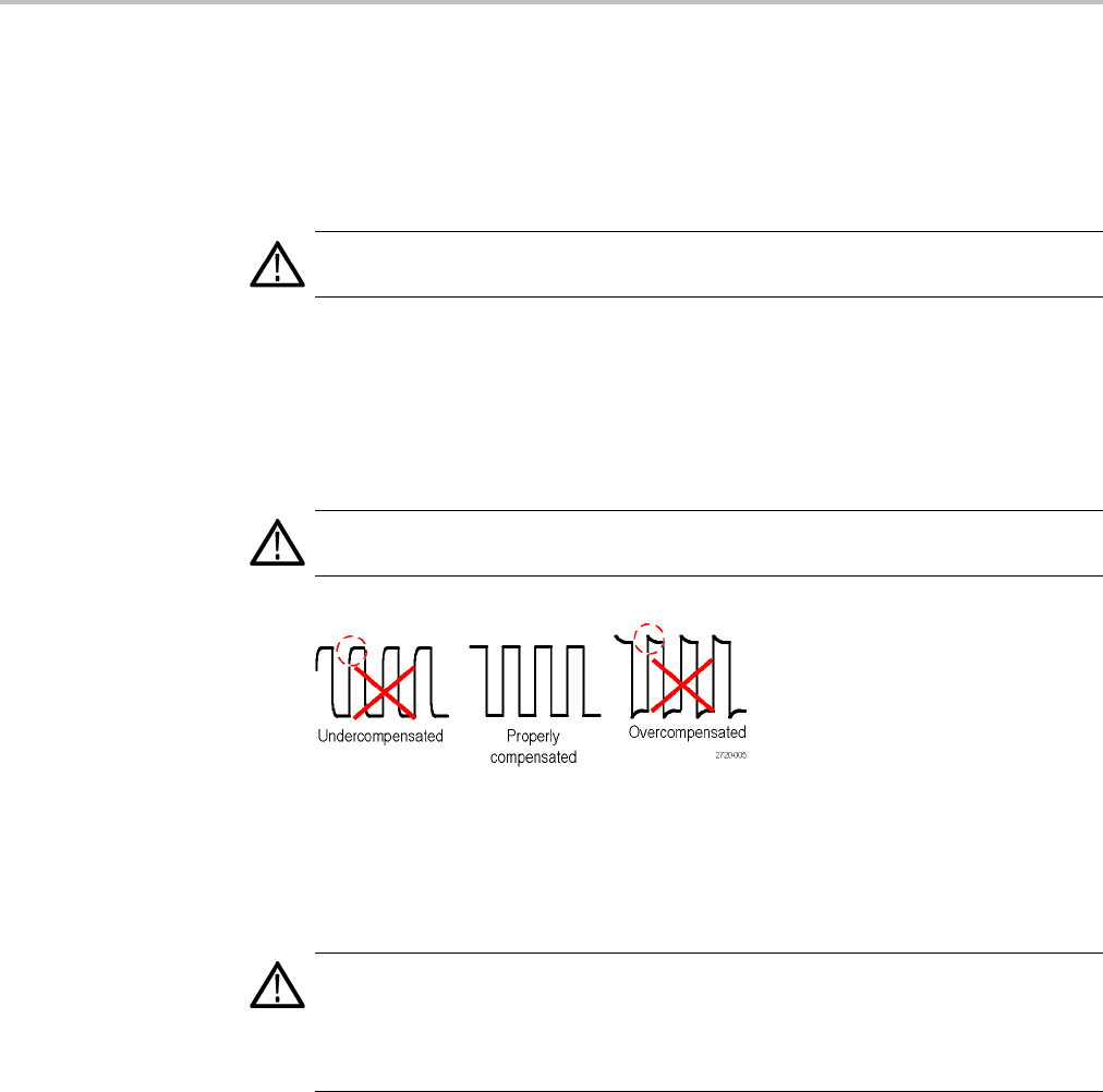
4. Adjust the trimmer in the probe until you see a perfectly flat-top square wave
on the display. (See illustration.)
WARNING. To avoid electric shock, only use the insulated adjustment tool when
making compensation adjustments.
Connecting the Probe to the Circuit
Use the standard accessories included with the probe to connect to your circuit.
WARNING. To avoid electric shock when using the probe or accessories, keep
fingers behind the finger guard of the probe body and accessories.
To r
educe risk of shock, ensure the ground lead and ground spring are fully mated
before connecting the probe to the circuit under test.
116 TBS1000 Series Oscilloscopes User Manual


