
User manual
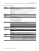
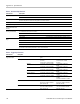
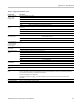
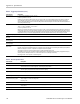

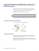
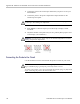
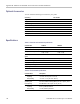
Table Of Contents
- toc
- General safety summary
- Compliance Information
- Preface
- Getting Started
- Operating Basics
- Understanding Oscilloscope Functions
- Application Examples
- Taking Simple Measurements
- Using Autorange to Examine a Series of Test Points
- Taking Cursor Measurements
- Analyzing Signal Detail
- Capturing a Single-Shot Signal
- Measuring Propagation Delay
- Triggering on a Specific Pulse Width
- Triggering on a Video Signal
- Analyzing a Differential Communication Signal
- Viewing Impedance Changes in a Network
- Data Logging
- Limit Testing
- Math FFT
- USB Flash Drive and Device Ports
- USB Flash Drive Port
- File Management Conventions
- Saving and Recalling Files With a USB Flash Drive
- Using the Save Function of the Print Front Panel Button
- USB Device Port
- Installing the PC Communications Software on a PC
- Connecting to a PC
- Connecting to a GPIB System
- Command Entry
- Connecting to a Printer
- Printing a Screen Image
- Reference
- Appendix A: Specifications
- Appendix B: TPP0101 and TPP0201 Series 10X Passive Probes Inform
- Appendix C: Accessories
- Appendix D: Cleaning
- Appendix E: Default Setup
- Appendix F: Font Licenses

Appendix A: Specifications
Table 5: Trigger Specifications (cont.)
Characteris
tic
Description
Equal Guardband t > 330 ns: ±5% ≤ guardband < ±(5.1% + 16.5 ns)
t ≤ 330 ns: gu
ardband = ±16.5 ns
All pulses, even from the most stable sources, have some amount of jitter. To avoid disqualifying pulses that are intended to qualify but
are not absolutely correct values, we provide an arbitrary guardband. Any measured pulse width within the guardband will qualify. If
looking fo
r pulse width differences that are smaller than the guardband width, offsetting the center should allow discriminating differences
down to the guardband accuracy.
Not Equal G
uardband
t > 330 ns: ±
5% ≤ guardband < ±(5.1% + 16.5 ns)
165 ns < t ≤ 330 ns: guardband = -16.5 ns/+33 ns
t ≤ 165 ns: guardband = ±16.5 ns
All pulse
s, even from the most stable sources, have some amount of jitter. To avoid disqualifying pulses that are intended to qualify but are
not absolutely correct values, we provide an arbitrary guardband. Any measured pulse width outside the guardband will qualify. If looking
for pulse width differences that are smaller than the guardband width, offsetting the center should allow discriminating differences down to
the guar
dband accuracy. Not equal has slightly better ability to deal with small pulse widths than equal. The accuracy is not better.
Trigge
r Frequency Counter
Frequency Counter
Resolu
tion
6 digits
Frequency Counter
Accur
acy (typical)
±51 parts per million including all frequency reference errors and ±1 count errors
Frequency Counter
Frequ
ency Range
AC coupled, 10 Hz minimum to rated bandwidth
Frequency Counter
Sign
al Source
Pulse width or edge selected trigger source
Frequency counter measures selected trigger source at all times in pulse width and edge mode, including when oscilloscope acquisition is
halt
ed due to changes in run status, or acquisition of a single shot event has completed.
The frequency counter does not measure pulses that do not qualify as legitimate trigger events.
Pulse Width mode: Counts pulses of sufficient magnitude inside the 250 ms measurement window that qualify as triggerable events (e.g.
all
narrow pulses in a PWM pulse train if set to < mode and the limit is set to a relatively small number).
Edge Trigger mode: Counts all pulses of sufficient magnitude.
Table 6: General Specifications
Characteristic
Description
Display
D
isplay Type
11.5 cm (W) x 8.64 cm (H), 14.38 cm diagonal, ¼ VGA, active TFT color liquid crystal display (LCD) with color
characters/waveforms on a black background. Surface anti-glare (3H) treatment
D
isplay Resolution
3
20 horizontal by 240 vertical pixels
The video display comprises both the character and waveform displays.
Brightness, typical
400 cd/ m
2
typical, 320 cd/m
2
min.
Probe Compensator Output
Probe Compensator, Output
Voltage and Frequency, typical
Characteristics are as follows:
Output voltage 5.0 V ±10% into 1 Meg Ω load
Frequency 1 kHz
Power Source
Source Voltage Full Range: 100 to 240 VAC RMS ±10%, Installation Category II (Covers range of 90 to 264 VAC); 50/60 Hz. 115 VAC RMS
±10%; 400 Hz.
Power Consumption Less than 30 W at 90 to 264 VAC input.
112 TBS1000 Series Oscilloscopes User Manual