
User manual

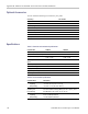
Table Of Contents
- toc
- General safety summary
- Compliance Information
- Preface
- Getting Started
- Operating Basics
- Understanding Oscilloscope Functions
- Application Examples
- Taking Simple Measurements
- Using Autorange to Examine a Series of Test Points
- Taking Cursor Measurements
- Analyzing Signal Detail
- Capturing a Single-Shot Signal
- Measuring Propagation Delay
- Triggering on a Specific Pulse Width
- Triggering on a Video Signal
- Analyzing a Differential Communication Signal
- Viewing Impedance Changes in a Network
- Data Logging
- Limit Testing
- Math FFT
- USB Flash Drive and Device Ports
- USB Flash Drive Port
- File Management Conventions
- Saving and Recalling Files With a USB Flash Drive
- Using the Save Function of the Print Front Panel Button
- USB Device Port
- Installing the PC Communications Software on a PC
- Connecting to a PC
- Connecting to a GPIB System
- Command Entry
- Connecting to a Printer
- Printing a Screen Image
- Reference
- Appendix A: Specifications
- Appendix B: TPP0101 and TPP0201 Series 10X Passive Probes Inform
- Appendix C: Accessories
- Appendix D: Cleaning
- Appendix E: Default Setup
- Appendix F: Font Licenses

Appendix A: Specifications
Table 5: Trigger Specifications (cont.)
Characteris
tic
Descripti on
The typical sensitivities are as follows:
Trigger Source Sensitivity
AC Same as DC Co
upled limits for frequencies 50 Hz and above
NOISE REJ Effective in Sample or Average Mode, >10 mV/div to 5 V/div. Reduces DC Coupled trigger sensitivity by 2X.
HF REJ
Same as DC Coupled limits from DC to 7 KHz.
Sensitivity, Edge-Type
Trigger, no
n-DC
Coupled, typical
LF REJ
Same as DC C
oupled limits for frequencies above 300 KHz.
The settable resolution for the trigger level is 0.02 division for an input channel source, 4 mV for an Ext source, and 20 mV for an
Ext/5 sou
rce.
Input channels
±8 divisions from center screen
EXT ± 1.6 V
Trigger Level Ranges,
typical
EXT/5
±8V
±(0.2 div +5 mV) for signals within ±4 divisions from center screen, having
rise and fall times of >20 ns
EXT
±(6% of setting + 40 mV) for signals less than ±800 mV
Trigge
r Level Accuracy,
DC Coupled, typical
EXT/5 ±(6% of
setting + 200 mV) for signals less than ±4 V
Lowest Frequency for
Succe
ssful Operation
of “Set Level to 50%”
Function, typical
50 Hz.
Trig
ger Mode
Auto
Default Settings for
Video Trigger
Trigger Coupling AC
A2d
ivision composite video signal will have a 0.6 division sync tip.
The typical sensitivities are as follows:
Source Typical Sensitivity
Inp
ut Channels
2di
visions of composite video
EXT
400 mV of composite video
Video Trigger Sensitivity,
typical
EXT/5 2Vofcompositevideo
Field rates: 50 Hz to 60 HzVideo Trigger Formats
a
nd Field Rates
L
ine rates:
15 kHz to 20 kHz (NTSC, PAL, SECAM)
T
rigger Hold Off Range
500 ns minimum to 10 s maximum
Pulse Width Trigger
Modes
< (Less than), > (Greater than), = (Equal), ≠ (Not Equal)
Pulse Width Trigger
Point
Equal: The oscilloscope triggers when the trailing edge of the pulse crosses the trigger level.
Not Equal: If the pulse is narrower than the specified width, the trigger point is the trailing edge. Otherwise, the oscilloscope triggers when
a pulse continues longer than the time specified as the Pulse Width.
Less than: The trigger point is the trailing edge.
Greater than (also called time-out trigger): The oscilloscope triggers when a pulse continues longer than the time specified as the
Pulse Width.
Pulse Width Range 33 ns ≤ width ≤ 10 sec
Pulse Width Resolution 16.5 ns or 1 part per thousand, whichever is larger
TBS1000 Series Oscilloscopes User Manual 111