
User manual

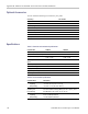
Table Of Contents
- toc
- General safety summary
- Compliance Information
- Preface
- Getting Started
- Operating Basics
- Understanding Oscilloscope Functions
- Application Examples
- Taking Simple Measurements
- Using Autorange to Examine a Series of Test Points
- Taking Cursor Measurements
- Analyzing Signal Detail
- Capturing a Single-Shot Signal
- Measuring Propagation Delay
- Triggering on a Specific Pulse Width
- Triggering on a Video Signal
- Analyzing a Differential Communication Signal
- Viewing Impedance Changes in a Network
- Data Logging
- Limit Testing
- Math FFT
- USB Flash Drive and Device Ports
- USB Flash Drive Port
- File Management Conventions
- Saving and Recalling Files With a USB Flash Drive
- Using the Save Function of the Print Front Panel Button
- USB Device Port
- Installing the PC Communications Software on a PC
- Connecting to a PC
- Connecting to a GPIB System
- Command Entry
- Connecting to a Printer
- Printing a Screen Image
- Reference
- Appendix A: Specifications
- Appendix B: TPP0101 and TPP0201 Series 10X Passive Probes Inform
- Appendix C: Accessories
- Appendix D: Cleaning
- Appendix E: Default Setup
- Appendix F: Font Licenses

Appendix A: Specifications
Table 3: Vertical Specifications (cont.)
Characteris
tic
Description
Analog Bandwidth, DC
Coupled, Pe
ak Detect,
typical
The Analog Bandwidth when the instrument is DC coupled. V/div values are accurate for probe attenuation settings of 1X. No
probe shoul
d be installed for t hese measurements.
TBS1154, TBS1152, TBS1104, and TBS1102: DC to ≥75 MHz for 5 mV/div through 5 V/div settings with bandwidth limit at full.
Setting less than 5 mV/div are limited to 20 MHz bandwidth.
TBS1064, T
BS1062: DC to ≥50 MHz for 5 mV/div through 5 V/div settings with bandwidth limit at full. Settings less than 5 mV/div are
limited to 20 MHz bandwidth.
TBS1042: DC to ≥30 MHz for 5 mV/div through 5 V/div settings with bandwidth limit at full. Setting less than 5 mV/div are limited to
20 MHz ban
dwidth.
TBS1022: DC to ≥20 Mhz for 5 mV for 5 mV/div through 5 V/div settings with bandwidth limit at full.
Analog Bandwidth
Selecti
ons
20 MHz BW L
imit ON/OFF
Lower Frequency Limit, AC
Coupled
≤ 10 Hz
≤1 Hz when 10X passive probes are used.
Rise Ti
me, typical
Rise time is generally calculated from the following formula: Rise time in ns = 350 / Bandwidth in MHz
TBS1154, TBS1152: The expected full bandwidth rise time: 2.6 ns.
TBS110
4, TBS1102: The expected full bandwidth rise time: 3.5 ns.
TBS1064, TBS1062: The expected full bandwidth rise time: 6.0 ns.
TBS1042: The expected full bandwidth rise time: 8.8 ns.
TBS10
22: The expected full bandwidth rise time: 14.0 ns.
The capability of the instrument to capture single event pulses using Peak Detect Acquisition Mode.
The m
inimum single pulse widths for guaranteed 50% or greater amplitude capture are as follows:
Sec/Div Setting
Minimum Pulse Width
50 s/div to 5 us/div
TBS
1154, TBS1152, TBS1104, TBS1102, TBS1064, TBS1062
12 ns
Peak Detect Mode Pulse
Response
TBS1022, TBS1042
13 ns
DC Gain Accuracy, Sample
or Average Acquisition
±3%, 5 V/div through 10 mV/div.
±4%, 5 mV/div and 2 mV/div.
The accuracy of DC voltage measurements acquired using Average of ≥ 16 waveforms.
Vertical Position = 0
±(
3% of |reading| + 0.1 div + 1 mV).
Vertical Position ≠ 0and
Vertical Scale
2
mV/div to 200 mV/div:
±[3% of (|reading + vertical position|) + 1% of |vertical position| + 0.2 div + 7 mV]
DC Voltage Measurement
Accuracy, Average
Ac
quisition Mode
Vertical Position ≠ 0, and
Vertical Scale >200 mV/div
±[3% of (|reading + vertical position|) + 1% of |vertical position| + 0.2 div + 175 mV]
Delta Volts between any two averages of 16 waveforms acquired under the same setup and ambient conditions
Delta Volts Measurement
Accuracy, Average
Acquisition Mode
(3% of |reading| + 0.05 div)
Volts/Division Setting
Position Accuracy
2 mV/div to 200 mV/div ±((1% * |selected value|) + 0.1 div + 5 mV) within the range
±1.8 V
Vertical Position Accuracy
> 200 mV/div to 5 V/div ±((1% * |selected value|) + 0.1 div + 125 mV) within the range
±45 V
TBS1000 Series Oscilloscopes User Manual 109