User manual
Table Of Contents
- toc
- General safety summary
- Compliance Information
- Preface
- Getting Started
- Operating Basics
- Understanding Oscilloscope Functions
- Application Examples
- Taking Simple Measurements
- Using Autorange to Examine a Series of Test Points
- Taking Cursor Measurements
- Analyzing Signal Detail
- Capturing a Single-Shot Signal
- Measuring Propagation Delay
- Triggering on a Specific Pulse Width
- Triggering on a Video Signal
- Analyzing a Differential Communication Signal
- Viewing Impedance Changes in a Network
- Data Logging
- Limit Testing
- Math FFT
- USB Flash Drive and Device Ports
- USB Flash Drive Port
- File Management Conventions
- Saving and Recalling Files With a USB Flash Drive
- Using the Save Function of the Print Front Panel Button
- USB Device Port
- Installing the PC Communications Software on a PC
- Connecting to a PC
- Connecting to a GPIB System
- Command Entry
- Connecting to a Printer
- Printing a Screen Image
- Reference
- Appendix A: Specifications
- Appendix B: TPP0101 and TPP0201 Series 10X Passive Probes Inform
- Appendix C: Accessories
- Appendix D: Cleaning
- Appendix E: Default Setup
- Appendix F: Font Licenses

Reference
Default Setup
Push the Default Setup button to recall most of the factory option and control
settings, but not all. Appendix D lists the default settings that will be recalled.
Display
Push the Display button to choose how waveforms are presented and to change
the appear
ance of the entire display.
Options Settings Comments
Ty pe Ve ctors, Dots
Vectors fill the space between adjacent
sample po
ints in the display
Dots display only the sample points
Persist
OFF, 1 sec , 2 sec,
5sec,Infinite
Sets the length of time each displayed
sample point remains displayed
Format YT, XY
YT format displays the vertical voltage in
relati
on to time (horizontal scale)
XY format displays a dot each time a sample
is acquired on channel 1 and channel 2
Channe
l 1 voltage or current determines the
X coordinate of the dot (horizontal) and the
channel 2 voltage or current determines the
Y coor
dinate (vertical)
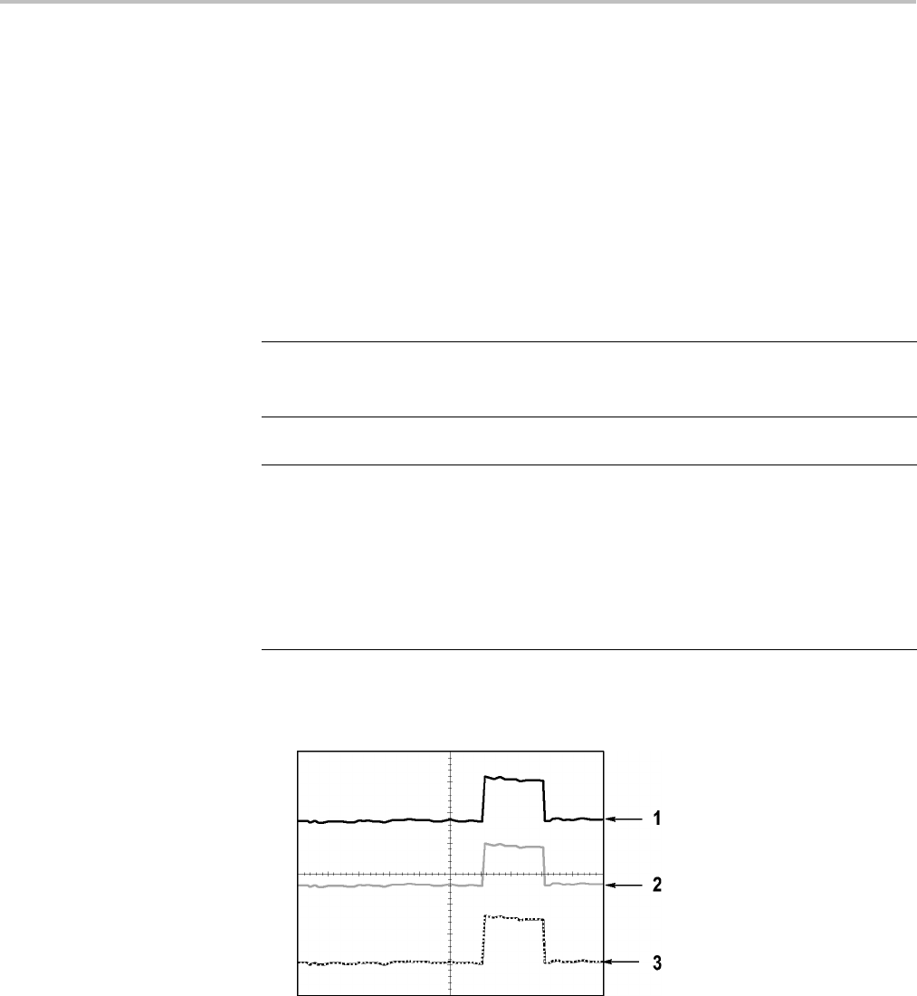
Depending on the type, waveforms will be displayed in three different styles:
solid, dimmed, and broken.
1. A solid waveform indicates a channel (live) waveform display. The waveform
remains solid when the acquisition is stopped if no controls are changed that
make the display accuracy uncertain.
Changing the vertical and horizontal controls is allowed on stopped
acquisitions.
TBS1000 Series Oscilloscopes User Manual 83


