
Data Sheet


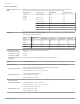

Application SV28 enables the following LTE base station transmitter
measurements:
Cell ID
Channel Power
Occupied Bandwidth
Adjacent Channel Leakage Ratio (ACLR)
Spectrum Emission Mask (SEM)
Transmitter Off Power for TDD
Reference Signal (RS) Power
There are four presets to accelerate pre-compliance testing and determine
the Cell ID. These presets are defined as Cell ID, ACLR, SEM, Channel
Power and TDD Toff Power. The measurements follow the definition in
3GPP TS Version 12.5 and support all base station categories, including
picocells and femtocells. Pass/Fail information is reported and all channel
bandwidths are supported.
The Cell ID preset displays the Primary Synchronization Signal (PSS) and
the Secondary Synchronization Signal (SSS) in a Constellation diagram. It
also provides Frequency Error.
The ACLR preset measures the E-UTRA and the UTRA adjacent channels,
with different chip rates for UTRA. ACLR also supports Noise Correction
based on the noise measured when there is no input. Both ACLR and SEM
will operate in swept mode (default) or in faster single acquisition (real-time)
when the measurement bandwidth required is less than 40 MHz.
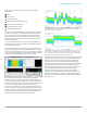
The signal classification application (SV54) enables expert systems
guidance to aid the user in classifying signals. It provides graphical tools
that allow you to quickly create a spectral region of interest, enabling you to
classify and sort signals efficiently. The spectral profile mask, when overlaid
on top of a trace, provides signal shape guidance, while frequency,
bandwidth, channel number, and location are displayed allowing for quick
checks. WLAN, GSM, W-CDMA, CDMA, Bluetooth standard and enhanced
data rate, LTE FDD and TDD, and ATSC signals can be quickly and simply
classified. Databases can be imported from your H500/RSA2500 signal
database library for easy transition to the new software base.
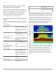
Above is a typical signal survey. This survey is of a portion of the TV broadcast band,
and 7 regions have been declared as either Permitted, Unknown, or Unauthorized, as
indicated by the color bars for each region.
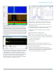
In this illustration, a single region has been selected. Since we have declared this to be
an ATSC video signal, the spectrum mask for the ATSC signal is shown overlaid in the
region. The signal is a close match to the spectrum mask, including the vestigial carrier
at the lower side of the signal, characteristic of ATSC broadcasts.
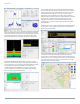
SignalVu-PC with mapping can be used to manually indicate the azimuth of
a measurement made in the field, greatly aiding in triangulation efforts. The
addition of a smart antenna able to report its direction to SignalVu-PC
automates this process. Automatically plotting the azimuth/bearing of a
measurement during interference hunting can greatly speed the time spent
searching for the source of interference. Tektronix offers the Alaris DF-
A0047 handheld direction finding antenna with frequency coverage from
20 MHz -8.5 GHz (optional 9 kHz-20 MHz) as part of a complete
interference hunting solution. Azimuth information and the selected
measurement is automatically recorded on the SignalVu-PC Map just by
releasing the control button on the antenna. Full specifications for the DF-
A0047 antenna are available in a separate antenna datasheet available on
www.Tektronix.com.
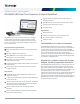
RSA306B USB Spectrum Analyzer
www.tek.com 5