
User Manual


Connecting signals
Connecting si
gnals
Input overview
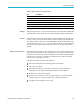
WARNING. To avoid possible electric shock or personal injury:
Do not touch connections, internal circuits, or measuring devices that are not
connected to earth ground.
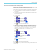
Always adhere to the instructions regarding the sequence of connections. (See
page 2, Connection sequence.)
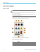
Signals are connected to the instrument on the rear of the power analzyer. There
are m ultiple inputs for each analog card a s shown below.
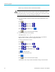
Figure 17: Signal inputs o n rear panel (Channel 1 shown)
Table 2: Signal inputs on rear panel
Item Description
1
Voltage high connection (VHI)
2
Voltage low connection (VLO)
3
T1AH, 250 V fuse to protect the 1 A shunt
28 PA3000 Power Analyzer User Manual