
User Manual


Reference information
Auxiliary inpu
ts/outputs.
The PA3000 is fitted with a number of auxiliary inputs and outputs. They are:
4 analog inputs
2 counter inputs
4 digital outputs
The pin conn
ections on the auxiliary connect are:
Table 24: Auxiliary input-output pin descriptions
Pin Signal name Pin Signal name
1 Analog Input 1
7
Digital Output 3
2 Analog Input 2 8
Digital Output 4
3 Analog Input 3 9
Counter Input 1
4 Analog Input 4 10
Counter Input 2
5
Digital Output 1
6
Digital Output 2
Pins 11 through 22 are connected to ground. Pins 23 through 25 have no
connection.
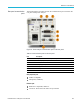
Serial port.
9-pin male D-type connector on rear of instrument
RS-232 interface for connection to a PC for remote control with a straight
through cable
Available baud rates 9600, 19200, and 38400 (default)
8 data bits, no parity, one stop bit, hardware flow control
Table 25: RS-232 connector pin descriptions
Pin I/O Signal name Pin I/O Signal name
1 No connection 6 No connection
2
Out
TXD
7
In
RTS
3In RXD 8
Out CTS
4 No connection 9 No connection
5
Ground
PA3000 Power Analyzer User Manual 149