
User Manual


Application examples
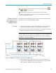
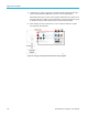
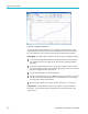
Figure 48: Auxiliary inputs setup for torque a nd speed measurements
Refer to the pin number for desired analog or counter input under Auxiliary
inputs/outputs and connect the signal (torque, speed, or others) directly to
the respective pin on the AUXILIARY INPUTS/OUTPUTS connector on
the rear panel.
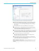
To enable the auxiliary inputs using PWRVIEW, go to the Setup tab.
On the Setup tab, go to the Wiring page and select the check box near the
bottom of the page for enabling the Auxiliary Inputs (Analog and Counters).
A new tab p age n amed Auxiliary Inputs will be created.
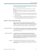
On the Auxiliary Inputs tab page, enter the desired label, units and equation for
the respective analog and counter inputs. Equation Guidelines on the bottom
can
be used for assistance with entering equations. Enable the desired inputs.
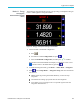
Go to the Measure tab page a nd click the Start button.
The selected analog and counter input s ignals will be displayed on the
measurement grid with proper labels and units.
Desired formulas for further equating system efficiency using analog and
counter inputs along with any other measurement parameters can be entered
i
n the Formula column on the measurement grid.
Waveform, Harmonics, and Trend chart. In the measurement grid, you can view
waveforms, harmonics, and trend charts by clicking the respective icons on the
menu bar.
PA3000 Power Analyzer User Manual 119