
User Manual


Application examples
Example 1: Effi
ciency testing single phase applications
The push towards green energy in recent years has raised the standards for
efficiency across all electronic and electrical products. Stricter ene rgy standards
such as Level
VI efficiency protocol, command tighter limits on efficiency
which makes it important to accurately measure input and output power and
simultaneously calculate efficiency over different load and source conditions.
This example d emonstrates a simple method to make efficiency measurements on
an external AC-DC power supply that is rated to the level VI efficiency standard.
Similar principles can also be applied to efficiency testing on any AC-DC power
supplies
, DC-AC inverters, and other related converters including solar inverter
and UPS systems.
Measurement challenge
Efficiency measurements are straight forward; they accurately me asure input
power an
d output power, and calculate efficiency over specified load and source
conditions. This example describes the setup and process for making accurate and
repeatable efficiency measurements on an external power supply. Make sure the
device under test is stable after the initial turn-on. A burn in time of 30 minutes
is recommended before taking any efficiency measurements. Many efficiency
standards also call for checking stability for about five minutes before taking the
final
measurement at a given load setting.
Measurement solutions
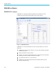
Efficiency can be measured directly on the PA3000 power analyzer display or
through the PWRVIEW software. The direct method is ideal for a quick test
and
monitoring; however, for long term testing and recording, the PWRVIEW
software is recommended. The PWRVIEW software makes it easy to configure,
monitor, set custom limits, and record efficiency meas urements. These features
are especially useful if you are measuring to energy efficiency standards w here
prolonged logging is required.
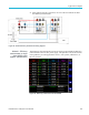
Test setup
Complete the following steps to set up the efficiency measurement on an AC-DC
power supply with the PA3000 Power Analyzer:
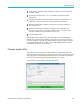
1. Connect the AC input on the device under test (DUT) to the first channel of
the PA3000 using a Tektronix Breakout Box (BB1000) as shown in the wiring
diagram. (See Figure 38 on page 105.)
The breakout b ox taps in to the current signal and measures the voltage across
the input terminals. It makes it easier and safer to connect the input AC signal
on the DUT using the 4 mm safety leads provided with PA3000.
2. Connect the output DC terminals on the second channel of the PA3000 using
the provided safety leads. The current shunt on the PA3000 is connected in
series with the output load; the voltage channe ls are connected across the
positive and negative terminals of the power supply as show in the figure.
104 PA3000 Power Analyzer User Manual