
Datasheet

Application Note
www.tektronix.com/power6
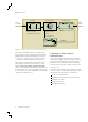
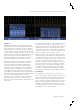
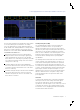
Figure 10. Bandwidth Limiting Filters Available on an MSO/DPO4000B Series
Oscilloscope with a TDP1000 Attached.
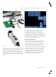
Degauss
A current probe should also include an easy to use
degaussing feature. Degauss removes any residual DC flux in
the core of the transformer, which may be caused by a large
amount of input current. This residual flux results in an output
offset error that should be removed to increase the accuracy
of the measurements being made.
Tektronix TekVPI current probes offer a Degauss warning
indicator that alerts the user to perform a degauss operation.
Since current probes may have significant drift over time which
affects measurement accuracy, a degauss warning indicator is
a useful feature.
Bandwidth Limiting Filters
Limiting the oscilloscope’s bandwidth removes noise or
unwanted high frequency content from the displayed
waveform, resulting in a cleaner signal. The MDO/MSO/
DPO4000 and MDO/MSO/DPO3000 Series offers built-in
bandwidth limiting filters, as shown in Figure 10. In some
cases, the probe may also be equipped with bandwidth
limiting filters.
The user should be careful when using these filters, as high
frequency content contained in nth order harmonics may be
removed from the measurement. For example, if measuring
a 1 MHz signal, and evaluating out to the 40th harmonic,
at least 40 MHz of system bandwidth is required. Setting
the bandwidth limiting filter to 20 MHz, which is an available
option in the example shown in Figure 10, would eliminate the
frequency content required for this measurement.
Power Supply Measurements
Once the measurement system is properly set up, the task
of performing power measurements can begin. The common
power measurements can be divided into three categories:
input analysis, switching device analysis and output analysis.
Input Analysis
Real-world electrical power lines never supply ideal sine
waves, and there is always some distortion and impurity
on the line. A switching power supply presents a non-linear
load to the source. Because of this, the voltage and current
waveforms are not identical. Current is drawn for some portion
of the input cycle, causing the generation of harmonics on the
input current waveform. Key measurements for analyzing the
input of the power supply are:
Harmonics
Power Quality