
Datasheet

www.tektronix.com/oscilloscopes 5
Debugging Serial Buses in Embedded System Designs
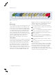
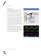
the I
2
C bus, so we decide to set up a trigger event to look
for a write to address 18 (the fan speed controller polling the
sensor for the current temperature). The triggered acquisition
is shown in the screenshot Figure 7.
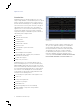
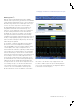
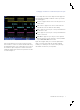
Working with I
2
C
With the optional serial triggering and analysis capability,
Tektronix oscilloscopes become a powerful tool for embedded
system designers working with I
2
C buses. The front panel has
Bus buttons that allow the user to define inputs to the scope
as a bus. The I
2
C bus setup menu is shown in Figure 5.
By simply defining which channels clock and data are on,
along with the thresholds used to determine logic ones
and zeroes, you’ve enabled the oscilloscope to understand
the protocol being transmitted across the bus. With this
knowledge, the oscilloscope can trigger on any specified
message-level information and then decode the resulting
acquisition into meaningful, easily interpreted results. Gone are
the days of edge triggering, hoping you acquired the event of
interest, and then manually decoding message after message
while looking for the problem.
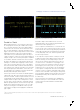
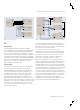
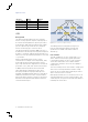
As an example, consider the embedded system in Figure 6.
An I
2
C bus is connected to multiple devices including a
CPU, an EEPROM, a fan speed controller, a digital to analog
converter (DAC), and a couple of temperature sensors.
This instrument was returned to engineering for failure analysis
as the product was consistently getting too hot and shutting
itself off. The first thing to check is the fan controller and the
fans themselves, but they both appear to be working correctly.
The next thing to check for is a faulty temperature sensor.
The fan speed controller polls the two temperature sensors
(located in different areas of the instrument) periodically and
adjusts the fan speed to regulate internal temperature. We
are suspicious that one or both of these temperature sensors
is not reading correctly. To see the interaction between the
sensors and the fan speed controller, we simply need to
connect to the I
2
C clock and data lines and set up a bus.
We know that the two sensors are addresses 18 and 19 on
Figure 5. I
2
C bus set-up menu.
Figure 6. I
2
C bus example.
Figure 7. I
2
C address and data bus waveform decoding.
CPU
SCLK (clock)
SDA (data)
EEPROM
DAC
Fan Speed Controller
Temperature Sensor 1
Temperature Sensor 2