
Datasheet


Application Note
www.tektronix.com/oscilloscopes4
I
2
C
Background
I
2
C, or “I squared C”, stands for Inter-Integrated Circuit. It was
originally developed by Philips in the early 1980s to provide
a low-cost way of connecting controllers to peripheral chips
in TV sets, but has since evolved into a worldwide standard
for communication between devices in embedded systems.
The simple two-wire design has found its way into a wide
variety of chips like I/O, A/Ds, D/As, temperature sensors,
microcontrollers and microprocessors from numerous leading
chipmakers including: Analog Devices, Atmel, Infineon,
Cyprus, Intel, Maxim, Philips, Silicon Laboratories, ST
Microelectronics, Texas Instruments, Xicor, and others.
How It Works
I
2
C’s physical two-wire interface is comprised of bi-directional
serial clock (SCL) and data (SDA) lines. I
2
C supports multiple
masters and slaves on the bus, but only one master may
be active at a time. Any I
2
C device can be attached to the
bus allowing any master device to exchange information
with a slave device. Each device is recognized by a unique
address. A device can operate as either a transmitter or a
receiver, depending on its function. Initially, I
2
C only used 7-bit
addresses, but evolved to allow 10-bit addressing as well.
Three bit rates are supported: 100 kb/s (standard mode),
400 kb/s (fast mode), and 3.4 Mb/s (high-speed mode). The
maximum number of devices is determined by a maximum
capacitance of 400 pF or roughly 20-30 devices.
The I
2
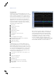
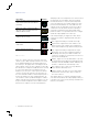
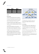
C standard specifies the following format in Figure 4:
Start - indicates the device is taking control of the bus and
that a message will follow.
Address - a 7 or 10 bit number representing the address of
the device that will either be read from or written to.
R/W Bit - one bit indicating if the data will be read from or
written to the device.
Ack - one bit from the slave device acknowledging the
master’s actions. Usually each address and data byte has
an acknowledge, but not always.
Data - an integer number of bytes read from or written to
the device.
Stop - indicates the message is complete and the master
has released the bus.
There are two ways to group I
2
C addresses for decoding: in
7-bits plus a read or write (R/W) bit scheme, and in 8-bits (a
byte) where the R/W bit is included as part of the address.
The 7-bit address scheme is the specified I
2
C Standard
followed by firmware and software design engineers. But
many other engineers use the 8-bit address scheme. Tektronix
oscilloscopes can decode data in either scheme.
Figure 4. I
2
C message structure.
Start
7 or 10 bits 1 bit
R/W
1 bit
Ack
8 bits
Data0
1 bit
Ack0
8 bits
Data1
1 bit
Ack1
1 bit
...
8 bits
DataN
1 bit
AckN StopAddress