
Datasheet


www.tektronix.com/oscilloscopes 37
Debugging Serial Buses in Embedded System Designs
How it Works
The D-PHY physical layer specifies a high-speed serial link
between a host processor and another device such as a
display or a camera. A minimum bus configuration is a clock
lane and a single data lane; however, up to four data lanes can
be used for increased bus bandwidth.
Buses operate in one of two modes; low-power and high-
speed. Low-power mode uses single-ended signaling and
embeds the clock in the data. It is typically used for command
and control purposes and has a maximum data transfer rate
of 10 Mb/s. High-speed mode uses differential signaling and is
typically used for fast data transfer. For example, a cell phone
display’s vertical and horizontal synchronization information
may be transmitted in low-power mode as relatively little
information needs to be transmitted and low transfer rates are
adequate. However, the actual video content displayed on the
phone requires large, high-speed data transfers to support
today’s high resolution displays and thus, utilizes high-speed
mode. While the actual maximum transfer rate in high-speed
mode is implementation-specific, the overall bus will typically
operate in the 80 Mb/s – 1 Gb/s range, per lane.
The DSI-1 and CSI-2 protocols specify that information
is transmitted across the D-PHY physical layer using a
combination of short packets and long packets.
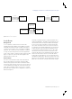
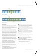
Short packets are typically used for command and control
type information such as synchronization and configuration
while long packets are typically used for video content. Short
packets are structured as follows:
Data Identifier – eight bits that include the Virtual Channel
and Data Type fields which are discussed next.
Virtual Channel – the virtual channel field specifies which
device on the bus the packet is intended for when more
than one camera or display device is on the bus. With two
bits, up to four devices can share a single bus.
Data Type – These six bits specify what type of command
or action is being sent and what the data in the Packet Data
field represents and how it’s structured.
ECC – this is an error correction field that enables single
bit errors to be corrected and 2-bit errors to be detected in
short packets.
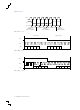
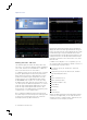
Long packets have a few more fields. Long packets are
structured as follows:
Virtual Channel, Data Type, and ECC are the same as in short
packets. Differences from short packets include:
Word Count – in a long packet, word count replaces
packet data. This 16 bit value specifies the number of
bytes included in the payload data.
Payload – This field is typically used to send large amounts
of video data via a number of different video formats. Each
format has its own Data Type. The payload field can be
anywhere from 0 to 65,535 (2
16
-1) bytes long.
Checksum – this field checks for errors in the payload.
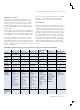
Data
identifier
Short
Packet
Low
Power
State
Low
Power
State
Virtual
Channel
(VC): 2 bits
Data Type
(DT): 6 bits
Packet Data
(PD):
16 bits
ECC: 8
bits
Start
Of
Transmission
End
Of
Transmission
Data
identifier
Long
Packet
Low
Power
State
Virtual
Channel
(VC): 2 bits
Data Type
(DT): 6 bits
Checksum:
16 bits
Word Count
(WC):
16 bits
ECC: 8
bits
Payload (Data):
0 to 2
16
-1 bytes
Start
Of
Transmission
Low
Power
State
End
Of
Transmission
Figure 49. Short MIPI packet.
Figure 50. Long MIPI packets.