
Datasheet


www.tektronix.com/oscilloscopes 31
Debugging Serial Buses in Embedded System Designs
Working with FlexRay
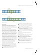
FlexRay serial triggering and analysis is available on several
Tektronix oscilloscope families (see Appendix A). To define a
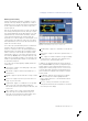
FlexRay bus, we go to the bus menu and select FlexRay from
the list of supported standards. The FlexRay setup menu is
shown in Figure 41.
Next, we use the Define Inputs menu to tell the scope whether
we’re looking at FlexRay channel A or B, what type of signal
we’re probing (differential, half the differential pair, or the logic
signal between the controller and the bus driver), and then
set the thresholds and the bit rate. FlexRay requires two
thresholds to be set when looking at non-Tx/Rx signals as it is
a three-level bus. This enables the oscilloscope to recognize
Data High and Data Low as well as the idle state where both
signals are at the same voltage.
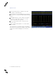
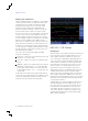
The oscilloscope's powerful FlexRay feature set is illustrated
in Figure 42 where we’ve triggered on a combination of
Frame ID = 4 and Cycle Count = 0, captured approximately
80 FlexRay frames, decoded the whole acquisition and then
had the oscilloscope search through the acquisition to find
and mark all occurrences of sync frames. And all of this was
done with only 100,000 point record lengths. With up to 250
million point record lengths available on some Tektronix scope
families, exceptionally long time windows of serial activity can
be captured and analyzed.
The oscilloscope's FlexRay triggering capability includes the
following types:
Start of Frame – triggers on the trailing edge of the Frame
Start Sequence (FSS).
Indicator Bits – trigger on Normal, Payload, Null, Sync, or
Startup frames.
Identifier – trigger on specific Frame IDs or a range of Frame
IDs.
Cycle Count – trigger on specific Cycle Count values or a
range of Cycle Count values.
Header Fields – trigger on a combination of user specified
values in any or all of the header fields including the
Indicator Bits, Frame ID, Payload Length, Header CRC, and
Cycle Count.
Data – trigger on up to 16 bytes of data. Data window
can be offset by a user specified number of bytes in a
frame with a very long data payload. Desired data can be
specified as a specific value or a range of values.
Identifier & Data – trigger on a combination of Frame ID and
data.
End of Frame – trigger on static frames, dynamic frames, or
all frames.
Error – trigger on a number of different error types including
Header CRC errors, Trailer CRC errors, Null frame errors,
Sync frame errors, and Startup frame errors.
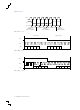
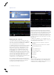
In addition to the triggering and decode features described
above, DPO4AUTOMAX also provides eye diagram analysis of
FlexRay signals to assist in diagnosing physical layer issues.
Simply load the software package on a PC, connect it to the
scope via LAN or USB, and click the Acquire Data button to
get the information rich display shown in Figure 43. Analysis
features include:
Eye Diagram – built from all messages in the acquisition
with the currently selected frame highlighted in blue.
Easily compare against TP1 or TP4 masks with violations
highlighted in red.
Decode – currently selected frame is decoded over the
analog waveform while the whole acquisition is decoded in
the bottom part of the display.
Figure 43. DPO4AUTOMAX Eye Diagram analysis of a FlexRay signal.