
Datasheet

Application Note
www.tektronix.com/oscilloscopes16
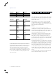
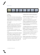
The Ethernet data frame format is defined by the IEEE 802.3
standard and contains seven fields, as shown in Figure 24.
The Preamble is seven bytes long consisting of an alternating
pattern of ones and zeros for synchronization.
The Start-of-frame Delimiter is a single byte with alternating
ones and zeros but ending in two ones.
The Destination and Source Media Access Control (MAC)
Addresses are each six bytes long, transmitted in most-
significant to least-significant bit order. Each Ethernet node
is assigned a unique MAC address which is used to specify
both the destination and the source of each data packet. It
thus forms the basis of most of the Link layer (OSI Layer 2)
networking upon which upper layer protocols rely to produce
complex, functioning networks.
The Length/Type field is a two-byte value. If the decimal value
of Length/Type is ≤1500, it represents the number of data
bytes in the data field. If the value of Length/Type is >1536
(0x0600), it is an EtherType value which specifies the protocol
that is encapsulated in the payload of the Ethernet frame. (For
example, EtherType is set to 0x0800 for IPv4.)
The Data packet contains 46 to 1500 bytes. If the data is less
than 46 bytes long, the data field is padded to be 46 bytes long.
The Frame Check Sequence is a 32-bit cyclic redundancy
check (CRC) and provides error checking across the
Destination Address, Source Address, Length/Type and
Data fields.
Finally, after each frame has been sent, transmitters are
required to transmit a minimum of 12 bytes of idle characters
before transmitting the next frame, or they must remain idle
for an equal amount of time by de-asserting the transmit
enable signal.
Ethernet
Background
Ethernet is a family of frame-based computer networking
technologies for local area networks (LANs), initially developed
at Xerox PARC in the early 1970s. The first standard draft was
published in 1980 by the Institute of Electrical and Electronics
Engineers (IEEE). Approval of IEEE 802.3 CSMA/CD occurred
in 1982 and the international ISO/IEEE 802.3 standard was
approved in 1984.
How It Works
Two of the most common versions of Ethernet are 10BASE-T
and 100BASE-TX which are found on most personal
computers. The leading number represents the data rate in
Mb/s. BASE indicates that the signals are baseband signals
and there is no RF signal modulation. The T denotes the
twisted pair wires that are in the LAN cable that is used
between network nodes.
The popularity of 10BASE-T and 100BASE-TX and its
decreasing hardware implementation cost has caused it to be
incorporated in an increasing number of embedded systems
designs.
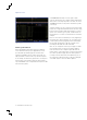
Ethernet provides peer-to-peer packet-based communication,
enabling direct point-to-point communication. At the physical
layer, the 10BASE-T and 100BASE-TX signals transport
address, control, data, and clock information. The data
is transferred in sequences of data bytes called packets.
Ethernet packets can carry other, higher-level protocol packets
inside of them. For example, an Ethernet packet may contain
an Internet Protocol (IP) packet, which in turn may contain
a Transmission Control Protocol (TCP) packet. This signal
complexity makes isolating events of interest difficult when
analyzing 10BASE-T and 100BASE-TX waveforms.
Figure 24. IEEE 802.3 standard Ethernet Frame Format.
Type Preamble
Start-of-
frame
Delimiter
Destination
Address
Source Ad-
dress
Length/
Type Data + Pad
Frame
check
sequence
Bytes 7 1 6 6 2 46-1500 4