
Datasheet

Application Note
www.tektronix.com/oscilloscopes12
In the J idle state, a low-speed device pulls D- high resulting
in a negative differential voltage. A full-speed device pulls D+
high resulting in a positive differential voltage. The K state is
opposite of the J state.
Data transmission uses non return to zero inverted (NRZI)
encoding with bit stuffing to ensure a minimum number of
transitions. The least significant bit is transmitted first and the
most significant bit is transmitted last.
Packets
The packets are the fundamental elements of USB
communications. Packets start with a synchronization field
followed by the packet identifier. After the packet identifier is
no field or other fields depending upon the type of packet. The
end-of-packet field terminates the packet.
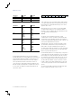
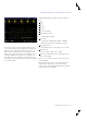
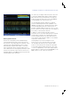
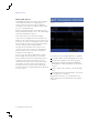
Starting from the J idle state, a packet starts with an 8-bit
synchronization (SYNC) field for low-speed and full-speed
USB. SYNC is 3 KJ pairs followed by two Ks (Figure 17).
The SYNC field for high-speed USB is 15 KJ pairs followed by
two Ks and hubs are allowed to reduce the repeating SYNC
field to 5 KJ pairs followed by two Ks.
Packet identifier (PID) is the second packet byte composed of
a 4-bit PID and its 4-bit PID complement for error checking. A
PID encoding error is when the first PID 4-bits do not match
the complement of the last PID 4-bits. Bits are sent out onto
the bus least-significant bit first and most-significant bit last.
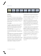
The PID 4-bit value identifies 17 types of packets as shown
in Table 4. Notice packet PRE and ERR have the same PID
code. Packet type groups are token, data, handshake and
special.
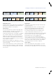
The end-of-packet (EOP) is three bits long. EOP starts with
two bits of SE0 and ends with one bit of J state.
A twisted differential pair Data+ (D+ green wire) and Data-
(D- white wire) wires are used for bidirectional communications
using half-duplex differential signaling controlled by the host.
Signal levels are listed in Table 3. The bus is DC coupled.
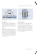
The host pulls down both D+ and D- when no device is
connected. This is called single-ended zero (SE0) state. The
USB bus voltage is pulled positive or negative when a device
is connected to the USB bus and the polarity indicates the
speed of the device.
Figure 17. Low-speed and full-speed SYNC field.
K J K J K J K K
Table 3. Electrical signal characteristics.
Table 4. USB packets types.
USB Speed Low State High State
Low-Speed <0.3V >2.8V
Full-Speed <0.3V >2.8V
High-Speed 0 V±10% 400 mV±10%
USB Speed Bit Rate Bit Period
Token OUT
IN
SOF
SETUP
0001
1001
0101
1101
Data DATA0
DATA1
DATA2
MDATA
0011
1011
0111
1111
Handshake ACK
NAK
STALL
NYET
0010
1010
1110
0110
Special PRE
ERR
SPLIT
PING
Reserved
1100
1100
1000
0100
0000