
User's Manual


Adjustments
P6330 3.5 GHz Differential Probe Instruction Manua l
49
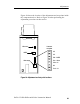
Figure 24 shows the l ocation of the adj ustments and t est poi nts inside
the compensation box. Refer to Figure 24 when performing the
adjustment procedures in this section.
Offset range
Offset zero
CMRR
Blk -- CMRR
Connector
test points
Blu -- Offset
Wht -- 5V
Red + 7V
NC
NC
NC
Figure 24: Adjustment and test point locations