
User's Manual


Performance Ve rification
P6330 3.5 GHz Differential Probe Instruction Manua l
43
Rise Time
This procedure verifies that the probe meets rise time specifications.
Two rise times are measured; the test system, and the test system
with the probe included. The probe rise time is calculated using the
two measurements.
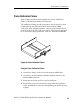
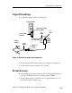
1. Connect the test equipment as shown i n Figure 20.
1103
Oscilloscope
CH 1
input
CH 1
output
BNC-to-SMA adapter
015-0572-00
SMA cable 015-0562-00
SD24/ 80E04
CH1
CH2
SMA cable 174-1427-00
BNC-to-SMA adapter
015-0572-00
Figure 20: Test system rise time setup
2. Adjust the oscilloscope vertical sensitivity to 50 mV/div.
3. Turn on the TDR pulse on the SD-24 or TDS8000 (Ch 2).
4. Adjust the oscilloscope vertical positioning to center the signal on
screen.
5. Adjust the oscilloscope horizontal sensitivity to 500 ps/div.
6. Adjust the oscilloscope horizontal positioning to place the rising
edge of the signal where it crosses the sec ond vertical and c enter
horizontal graticule lines.
7. Use the oscilloscope measurement capability to display rise time.
Rise time is determined from the 10% and 90% amplitude points
on the waveform. Record the rise time as t
s.