
User's Manual


Theory of Operation
34
P6330 3.5 GHz Differential Probe Instruction Manua l
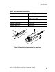
Probe Head and Cable Assembly
The probe head assembly contains an active amplifier circuit that
buffers and amplifies the input signal. The am plifier receives power
and an offset level from the compensation box assembly via the
cable assembly.
All signal amplification and buffering is performed in the probe head
assembly. No further amplification takes place in the compensation
box.
Compensation Box
The compensation box contains the following circuits:
H Offset amplifier
H Probe identification EEPROM
H TEKPROBE interface
H DC CMRR adjustment circuitry
H V
CC
, +7 V linear regulator
Offset Amplifier
The offset amplifier is used to offset the DC compone nt of the input
signal so that it stays at the optimal point of the linear dynamic range
of the probe.
The offset amplifier receives offset information as a ±1 VDC voltage
from the oscilloscope. The amplifier then amplifies it to match the
probe characteristics and applies it to the probe hybrid c ircuit.
The offset amplifier has two adjustments: offset zero and offse t gain.
These adjustments rarely need attention; however, detailed
adjustment instructions are in the Adjustments sectiononpage47.
Probe Identification EEPROM
The probe identification EEPROM is used to configure the
oscilloscope to the probe. The EEPROM receives a clock input from
the oscilloscope, and information about the probe is passed to the
oscilloscope.