
User's Manual


P6330 3.5 GHz Differential Probe Instruction Manua l
17
Functional Check
After installing the probe on the oscilloscope, a functional check
may be performed using the PROBE COMPENSATION connections
on the front panel of the oscilloscope. See Figure 8.
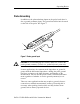
Figure 8: Probe functional check connections
1. Connect the probe to the oscilloscope.
2. Set the oscilloscope to display the probe channel.
3. Connect the square pin adapter to t he probe ti p, and conne ct the
Y-lead adapter to the square pin adapter. Plug the SMT KlipChips
into the Y-lead adapter.
4. Connect the SMT KlipChips to the PROBE COMPENSATION
connections on the oscilloscope.
5. Adjust the oscilloscope to display a stable calibration waveform.