
User's Manual


Table Of Contents
- Title page
- Table of Contents
- General Safety Summary
- Preface
- Getting Started
- Operating Basics
- Reference
- Reference
- Menu Structures
- The Setup Menu Screen
- The Graphical Waveform Editor
- The Pattern Editor
- Quick Editing
- The Table Editor
- The Equation Editor
- The Sequence Editor
- The APPL Menu
- The UTILITY Window
- External Keyboards
- Setting General Purpose Knob Direction
- Formatting a Floppy Disk
- Displaying Disk Usage
- Screen Display Enable/Disable
- Focused Color
- Displaying Instrument Status
- Internal Clock (Date and Time)
- Resetting the Instrument
- Connecting to a GPIB Network
- Ethernet Networking
- Hardcopy
- Calibration and Diagnostics
- Upgrading the System Software
- Capturing Waveforms
- Waveform Programming Language
- Command Descriptions
- Programming Examples
- File Conversion
- File Management
- FG Mode
- Waveform Mixing Mode
- Synchronous Operation Mode (AWG710B only)
- Appendices
- Appendix A: Specifications (AWG710B)
- Appendix A: Specifications (AWG710)
- Appendix B: Performance Verification (AWG710B)
- Conventions
- Self Tests
- Performance Tests
- Operating Mode Tests
- Amplitude and Offset Accuracy Tests (Normal Out), (except option 02)
- Amplitude, Offset Accuracy and Rise Time Tests (Direct DA Out), (except option 02)
- Amplitude, Offset Accuracy and Rise Time Tests (for option 02)
- Pulse Response Tests (Normal Out), (except option 02)
- Trigger Input Tests
- Event Input and Enhanced Mode Tests
- External Clock Input and VCO Out Output Tests
- VCO OUT Output Frequency and 10 MHz Reference Input Tests
- Marker Output Tests
- Synchronous Operation Tests
- Appendix B: Performance Verification (AWG710)
- Conventions
- Self Tests
- Performance Tests
- Operating Mode Tests
- Amplitude and Offset Accuracy Tests (Normal Out), (except option 02)
- Amplitude, Offset Accuracy and Rise Time Tests (Direct DA Out), (except option 02)
- Amplitude, Offset Accuracy and Rise Time Tests (for option 02)
- Pulse Response Tests (Normal Out), (except option 02)
- Trigger Input Tests
- Event Input and Enhanced Mode Tests
- 1/4 Clock Frequency and 10 MHz Reference Input Tests
- Marker Output Tests
- Appendix C: Inspection and Cleaning
- Appendix D: Sample Waveforms
- Appendix E: File Transfer Interface Outline
- Appendix F: Miscellaneous
- Appendix G: Sequence File Text Format
- Index
Operating Basics
2-12 AWG710&AWG710B Arbitrary Waveform Generator User Manual
Numeric Input
You can enter numeric values by using either the numeric keypad or the general
purpose knob. If the side menu item displays a value, you can alter this value using
the general purpose knob or numeric buttons.
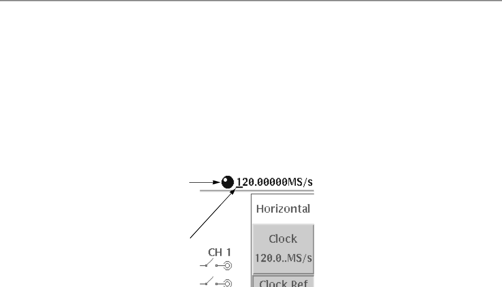
Pushing the type of side menu button or selecting a parameter in a pop–up menu
causes the current setting to appear on the right end of the Status Display area as
shown in Figure 2-11.
Figure 2-11: Knob icon displayed in Status Display area
The General Purpose Knob
A knob icon with a numeric value that includes an underscore character indicates
that you can change the value at the underscore location by using the general
purpose knob or keypad buttons. By default, the underscore character is positioned
under the digit specified depending on the parameters. You can only change the
value represented by the digits at and to the left of the underscore. Use the a and '
arrow buttons to move the underscore to the desired position, and then turn the
general purpose knob to change the value.
If the numeric value has the knob icon, but does not have the underscore, then
turning the general purpose knob cycles through a predefined set of values.
When using the general purpose knob, values you change in side menus and menu
screens take effect immediately. Values in pop–up menus are not effective until
you push the OK side button or the ENTER front–panel button.
The Numeric Keypad
Figure 2-12 shows the numeric keypad, with descriptions of the button operations.
Knob icon
Underscore