
User's Manual


Table Of Contents
- Title page
- Table of Contents
- General Safety Summary
- Preface
- Getting Started
- Operating Basics
- Reference
- Reference
- Menu Structures
- The Setup Menu Screen
- The Graphical Waveform Editor
- The Pattern Editor
- Quick Editing
- The Table Editor
- The Equation Editor
- The Sequence Editor
- The APPL Menu
- The UTILITY Window
- External Keyboards
- Setting General Purpose Knob Direction
- Formatting a Floppy Disk
- Displaying Disk Usage
- Screen Display Enable/Disable
- Focused Color
- Displaying Instrument Status
- Internal Clock (Date and Time)
- Resetting the Instrument
- Connecting to a GPIB Network
- Ethernet Networking
- Hardcopy
- Calibration and Diagnostics
- Upgrading the System Software
- Capturing Waveforms
- Waveform Programming Language
- Command Descriptions
- Programming Examples
- File Conversion
- File Management
- FG Mode
- Waveform Mixing Mode
- Synchronous Operation Mode (AWG710B only)
- Appendices
- Appendix A: Specifications (AWG710B)
- Appendix A: Specifications (AWG710)
- Appendix B: Performance Verification (AWG710B)
- Conventions
- Self Tests
- Performance Tests
- Operating Mode Tests
- Amplitude and Offset Accuracy Tests (Normal Out), (except option 02)
- Amplitude, Offset Accuracy and Rise Time Tests (Direct DA Out), (except option 02)
- Amplitude, Offset Accuracy and Rise Time Tests (for option 02)
- Pulse Response Tests (Normal Out), (except option 02)
- Trigger Input Tests
- Event Input and Enhanced Mode Tests
- External Clock Input and VCO Out Output Tests
- VCO OUT Output Frequency and 10 MHz Reference Input Tests
- Marker Output Tests
- Synchronous Operation Tests
- Appendix B: Performance Verification (AWG710)
- Conventions
- Self Tests
- Performance Tests
- Operating Mode Tests
- Amplitude and Offset Accuracy Tests (Normal Out), (except option 02)
- Amplitude, Offset Accuracy and Rise Time Tests (Direct DA Out), (except option 02)
- Amplitude, Offset Accuracy and Rise Time Tests (for option 02)
- Pulse Response Tests (Normal Out), (except option 02)
- Trigger Input Tests
- Event Input and Enhanced Mode Tests
- 1/4 Clock Frequency and 10 MHz Reference Input Tests
- Marker Output Tests
- Appendix C: Inspection and Cleaning
- Appendix D: Sample Waveforms
- Appendix E: File Transfer Interface Outline
- Appendix F: Miscellaneous
- Appendix G: Sequence File Text Format
- Index
Appendix D: Sample Waveforms
D-4 AWG710&AWG710B Arbitrary Waveform Generator User Manual
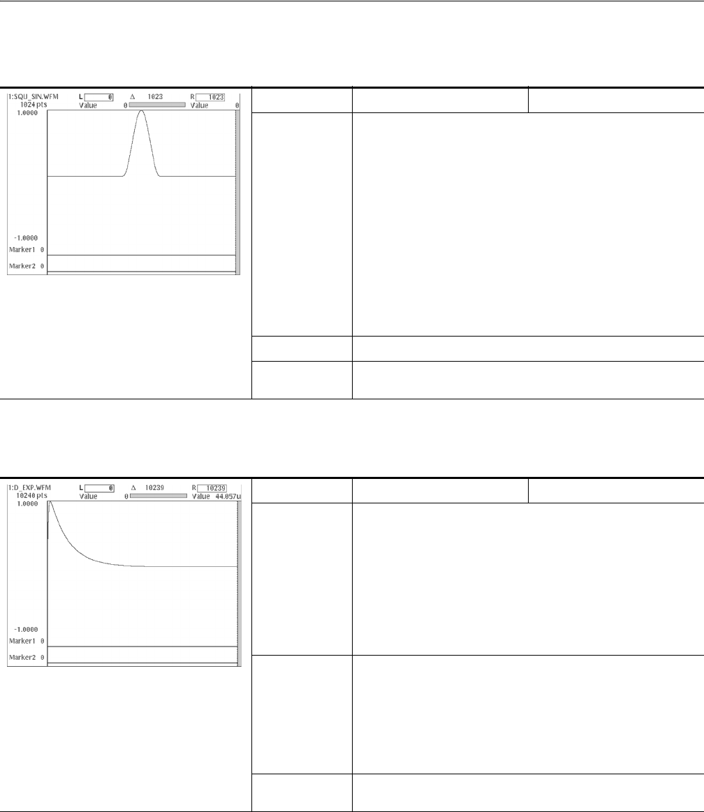
Table D-5: Squared sine pulse
File name SQU_SIN.WFM Made with equation editor
Equation
clock = 1e9
size = 412
“tmp1” = 0
size = 200
“tmp2” = (cos (2 * pi * (scale - 0.5)) + 1) / 2
“tmp3” = join (“tmp1”, “tmp2”)
“squ_sin.wfm” = join (“tmp3”, “tmp1”)
delete (“tmp1”)
delete (“tmp2”)
delete (“tmp3”)
Descriptions
Settings
Waveform points: 1024, Clock frequency: 1.0 GHz,
Output time: 412 ns
Table D-6: Double exponential pulse
File name D_EXP.WFM Made with equation editor
Equation
clock = 1e9
size = 10240
k1 = 50e-9 ’rise time constant
k2 = 1000e-9 ’fall time constant
“tmp” = exp (-time / k2) - exp (-time /k1)
“d_exp.efm” = norm (“tmp”)
delete (“tmp”)
Descriptions
This is the waveform when a charged capacitor is discharged to the
RC circuit. When the time constants for charging and discharging
are taken to be
τ
1
and τ
2
, respectively, the waveform can be
expressed by the following formula:
Settings
Waveform points: 10240, Clock frequency: 1.0 GHz,
Output time: 10240 ns
Vt()
t
τ
2
-----–
t
τ
1
-----–
exp–exp=