
User's Manual


Table Of Contents
- Title page
- Table of Contents
- General Safety Summary
- Preface
- Getting Started
- Operating Basics
- Reference
- Reference
- Menu Structures
- The Setup Menu Screen
- The Graphical Waveform Editor
- The Pattern Editor
- Quick Editing
- The Table Editor
- The Equation Editor
- The Sequence Editor
- The APPL Menu
- The UTILITY Window
- External Keyboards
- Setting General Purpose Knob Direction
- Formatting a Floppy Disk
- Displaying Disk Usage
- Screen Display Enable/Disable
- Focused Color
- Displaying Instrument Status
- Internal Clock (Date and Time)
- Resetting the Instrument
- Connecting to a GPIB Network
- Ethernet Networking
- Hardcopy
- Calibration and Diagnostics
- Upgrading the System Software
- Capturing Waveforms
- Waveform Programming Language
- Command Descriptions
- Programming Examples
- File Conversion
- File Management
- FG Mode
- Waveform Mixing Mode
- Synchronous Operation Mode (AWG710B only)
- Appendices
- Appendix A: Specifications (AWG710B)
- Appendix A: Specifications (AWG710)
- Appendix B: Performance Verification (AWG710B)
- Conventions
- Self Tests
- Performance Tests
- Operating Mode Tests
- Amplitude and Offset Accuracy Tests (Normal Out), (except option 02)
- Amplitude, Offset Accuracy and Rise Time Tests (Direct DA Out), (except option 02)
- Amplitude, Offset Accuracy and Rise Time Tests (for option 02)
- Pulse Response Tests (Normal Out), (except option 02)
- Trigger Input Tests
- Event Input and Enhanced Mode Tests
- External Clock Input and VCO Out Output Tests
- VCO OUT Output Frequency and 10 MHz Reference Input Tests
- Marker Output Tests
- Synchronous Operation Tests
- Appendix B: Performance Verification (AWG710)
- Conventions
- Self Tests
- Performance Tests
- Operating Mode Tests
- Amplitude and Offset Accuracy Tests (Normal Out), (except option 02)
- Amplitude, Offset Accuracy and Rise Time Tests (Direct DA Out), (except option 02)
- Amplitude, Offset Accuracy and Rise Time Tests (for option 02)
- Pulse Response Tests (Normal Out), (except option 02)
- Trigger Input Tests
- Event Input and Enhanced Mode Tests
- 1/4 Clock Frequency and 10 MHz Reference Input Tests
- Marker Output Tests
- Appendix C: Inspection and Cleaning
- Appendix D: Sample Waveforms
- Appendix E: File Transfer Interface Outline
- Appendix F: Miscellaneous
- Appendix G: Sequence File Text Format
- Index
Appendix B: Performance Verification (AWG710)
AWG710&AWG710B Arbitrary Waveform Generator User Manual B-71
e. Push 1, 0, 0 and M (SHIFT+7) keys in this order or turn the general
purpose knob to set the internal clock frequency to 100 MHz.
f. Push the RUN and CH1 output buttons.
The LEDs above the RUN button and CH1 output connector are on.
g. Push the FORCE TRIGGER button.
Verify that the oscilloscope displays sine waves while the FORCE TRIGGER
button is pushed and that the output stops when the Force Trigger button is
released.
4. Follow the substeps below to check the gated mode with the gate signal:
a. Set the oscilloscope trigger source to CH2 and change the trigger level to
1 V.
b. Turn on the function generator output.
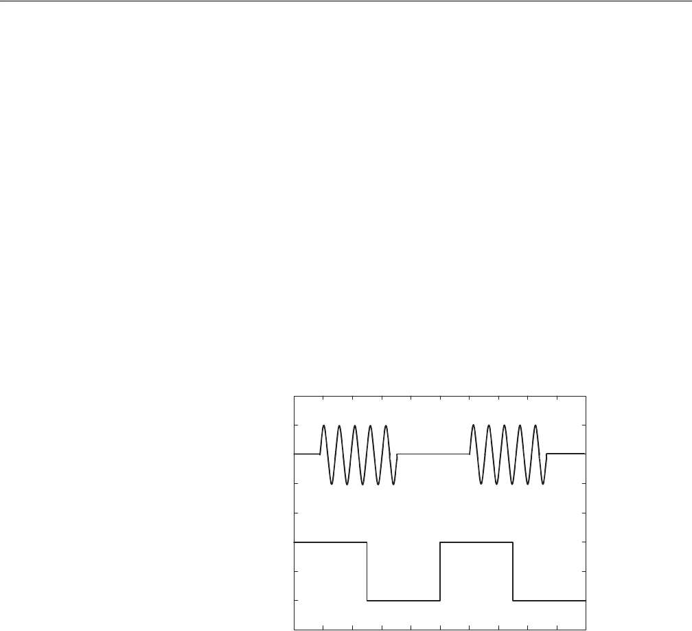
c. Verify that the oscilloscope displays sine waves while the function
generator gate signal amplitude is High level. See Figure B-42.
Figure B-42: Relationship between gate signal and waveform output
d. Push SETUP (front–panel)!Trigger (bottom)!Negative (side).
This changes the AWG710 Arbitrary Waveform Generator trigger polarity to
negative.
5. Verify that the oscilloscope displays sine waves while the function generator
gate signal amplitude is Low level.
6. Turn off the function generator output and disconnect from the oscilloscope.
Waveform
output
Gate
signal
CH1
CH2