
User's Manual


Table Of Contents
- Title page
- Table of Contents
- General Safety Summary
- Preface
- Getting Started
- Operating Basics
- Reference
- Reference
- Menu Structures
- The Setup Menu Screen
- The Graphical Waveform Editor
- The Pattern Editor
- Quick Editing
- The Table Editor
- The Equation Editor
- The Sequence Editor
- The APPL Menu
- The UTILITY Window
- External Keyboards
- Setting General Purpose Knob Direction
- Formatting a Floppy Disk
- Displaying Disk Usage
- Screen Display Enable/Disable
- Focused Color
- Displaying Instrument Status
- Internal Clock (Date and Time)
- Resetting the Instrument
- Connecting to a GPIB Network
- Ethernet Networking
- Hardcopy
- Calibration and Diagnostics
- Upgrading the System Software
- Capturing Waveforms
- Waveform Programming Language
- Command Descriptions
- Programming Examples
- File Conversion
- File Management
- FG Mode
- Waveform Mixing Mode
- Synchronous Operation Mode (AWG710B only)
- Appendices
- Appendix A: Specifications (AWG710B)
- Appendix A: Specifications (AWG710)
- Appendix B: Performance Verification (AWG710B)
- Conventions
- Self Tests
- Performance Tests
- Operating Mode Tests
- Amplitude and Offset Accuracy Tests (Normal Out), (except option 02)
- Amplitude, Offset Accuracy and Rise Time Tests (Direct DA Out), (except option 02)
- Amplitude, Offset Accuracy and Rise Time Tests (for option 02)
- Pulse Response Tests (Normal Out), (except option 02)
- Trigger Input Tests
- Event Input and Enhanced Mode Tests
- External Clock Input and VCO Out Output Tests
- VCO OUT Output Frequency and 10 MHz Reference Input Tests
- Marker Output Tests
- Synchronous Operation Tests
- Appendix B: Performance Verification (AWG710)
- Conventions
- Self Tests
- Performance Tests
- Operating Mode Tests
- Amplitude and Offset Accuracy Tests (Normal Out), (except option 02)
- Amplitude, Offset Accuracy and Rise Time Tests (Direct DA Out), (except option 02)
- Amplitude, Offset Accuracy and Rise Time Tests (for option 02)
- Pulse Response Tests (Normal Out), (except option 02)
- Trigger Input Tests
- Event Input and Enhanced Mode Tests
- 1/4 Clock Frequency and 10 MHz Reference Input Tests
- Marker Output Tests
- Appendix C: Inspection and Cleaning
- Appendix D: Sample Waveforms
- Appendix E: File Transfer Interface Outline
- Appendix F: Miscellaneous
- Appendix G: Sequence File Text Format
- Index
Appendix B: Performance Verification (AWG710B)
AWG710&AWG710B Arbitrary Waveform Generator User Manual B-31
Pulse Response Tests (Normal Out), (except option 02)
This procedure checks the pulse response characteristics of the AWG710B Arbitrary
Waveform Generator output waveforms at amplitudes of 1 V.
Do the following steps to install the test hookup and set the test equipment controls:
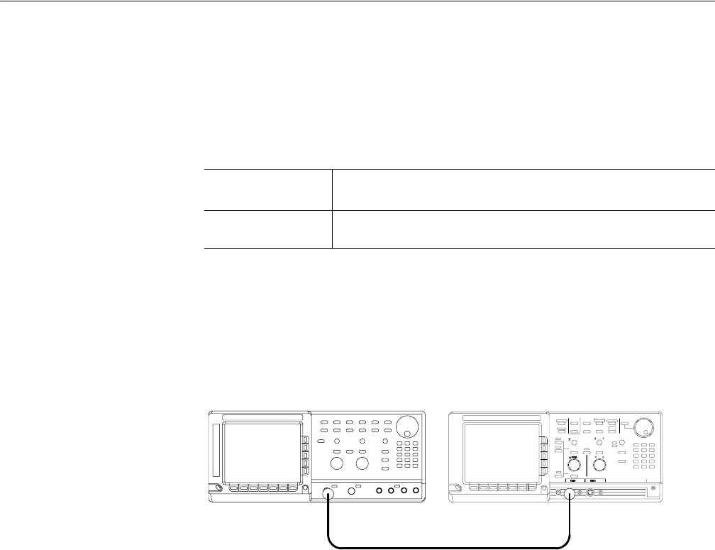
1. Use the 50 Ω SMA coaxial cable to connect the AWG710B Arbitrary
Waveform Generator CH1 output connector to the oscilloscope CH1 input
connector (see Figure B-14).
Figure B-14: Pulse response initial test hookup
2. Set the oscilloscope controls as follows:
3. Push UTILITY (front–panel)!System (bottom)!Factory Reset (side)
!OK (side).
Equipment
required
A 50 Ω SMA coaxial cable and an oscilloscope (TDS820).
Prerequisites
The AWG710B Arbitrary Waveform Generator must meet the
prerequisites listed on page B-7.
VerticalCH1
CH1 coupling. . . . . . . . . . . . . . . . . . . . . . . . . DC if applicable
CH1 scale . . . . . . . . . . . . . . . . . . . . . . . . . . . 200 mV/div
Horizontal
Sweep . . . . . . . . . . . . . . . . . . . . . . . . . . . . . . 500 ps/div
Trigger
Source. . . . . . . . . . . . . . . . . . . . . . . . . . . . . . CH1
Slope . . . . . . . . . . . . . . . . . . . . . . . . . . . . . . . Positive
Level . . . . . . . . . . . . . . . . . . . . . . . . . . . . . . . 0 V
Mode . . . . . . . . . . . . . . . . . . . . . . . . . . . . . . . Auto
AWG710B Arbitrary Waveform Generator Oscilloscope (TDS820)
50Ω SMA coaxial cable