
User's Manual


Table Of Contents
- Title page
- Table of Contents
- General Safety Summary
- Preface
- Getting Started
- Operating Basics
- Reference
- Reference
- Menu Structures
- The Setup Menu Screen
- The Graphical Waveform Editor
- The Pattern Editor
- Quick Editing
- The Table Editor
- The Equation Editor
- The Sequence Editor
- The APPL Menu
- The UTILITY Window
- External Keyboards
- Setting General Purpose Knob Direction
- Formatting a Floppy Disk
- Displaying Disk Usage
- Screen Display Enable/Disable
- Focused Color
- Displaying Instrument Status
- Internal Clock (Date and Time)
- Resetting the Instrument
- Connecting to a GPIB Network
- Ethernet Networking
- Hardcopy
- Calibration and Diagnostics
- Upgrading the System Software
- Capturing Waveforms
- Waveform Programming Language
- Command Descriptions
- Programming Examples
- File Conversion
- File Management
- FG Mode
- Waveform Mixing Mode
- Synchronous Operation Mode (AWG710B only)
- Appendices
- Appendix A: Specifications (AWG710B)
- Appendix A: Specifications (AWG710)
- Appendix B: Performance Verification (AWG710B)
- Conventions
- Self Tests
- Performance Tests
- Operating Mode Tests
- Amplitude and Offset Accuracy Tests (Normal Out), (except option 02)
- Amplitude, Offset Accuracy and Rise Time Tests (Direct DA Out), (except option 02)
- Amplitude, Offset Accuracy and Rise Time Tests (for option 02)
- Pulse Response Tests (Normal Out), (except option 02)
- Trigger Input Tests
- Event Input and Enhanced Mode Tests
- External Clock Input and VCO Out Output Tests
- VCO OUT Output Frequency and 10 MHz Reference Input Tests
- Marker Output Tests
- Synchronous Operation Tests
- Appendix B: Performance Verification (AWG710)
- Conventions
- Self Tests
- Performance Tests
- Operating Mode Tests
- Amplitude and Offset Accuracy Tests (Normal Out), (except option 02)
- Amplitude, Offset Accuracy and Rise Time Tests (Direct DA Out), (except option 02)
- Amplitude, Offset Accuracy and Rise Time Tests (for option 02)
- Pulse Response Tests (Normal Out), (except option 02)
- Trigger Input Tests
- Event Input and Enhanced Mode Tests
- 1/4 Clock Frequency and 10 MHz Reference Input Tests
- Marker Output Tests
- Appendix C: Inspection and Cleaning
- Appendix D: Sample Waveforms
- Appendix E: File Transfer Interface Outline
- Appendix F: Miscellaneous
- Appendix G: Sequence File Text Format
- Index
Appendix A: Specifications (AWG710)
AWG710&AWG710B Arbitrary Waveform Generator User Manual A-37
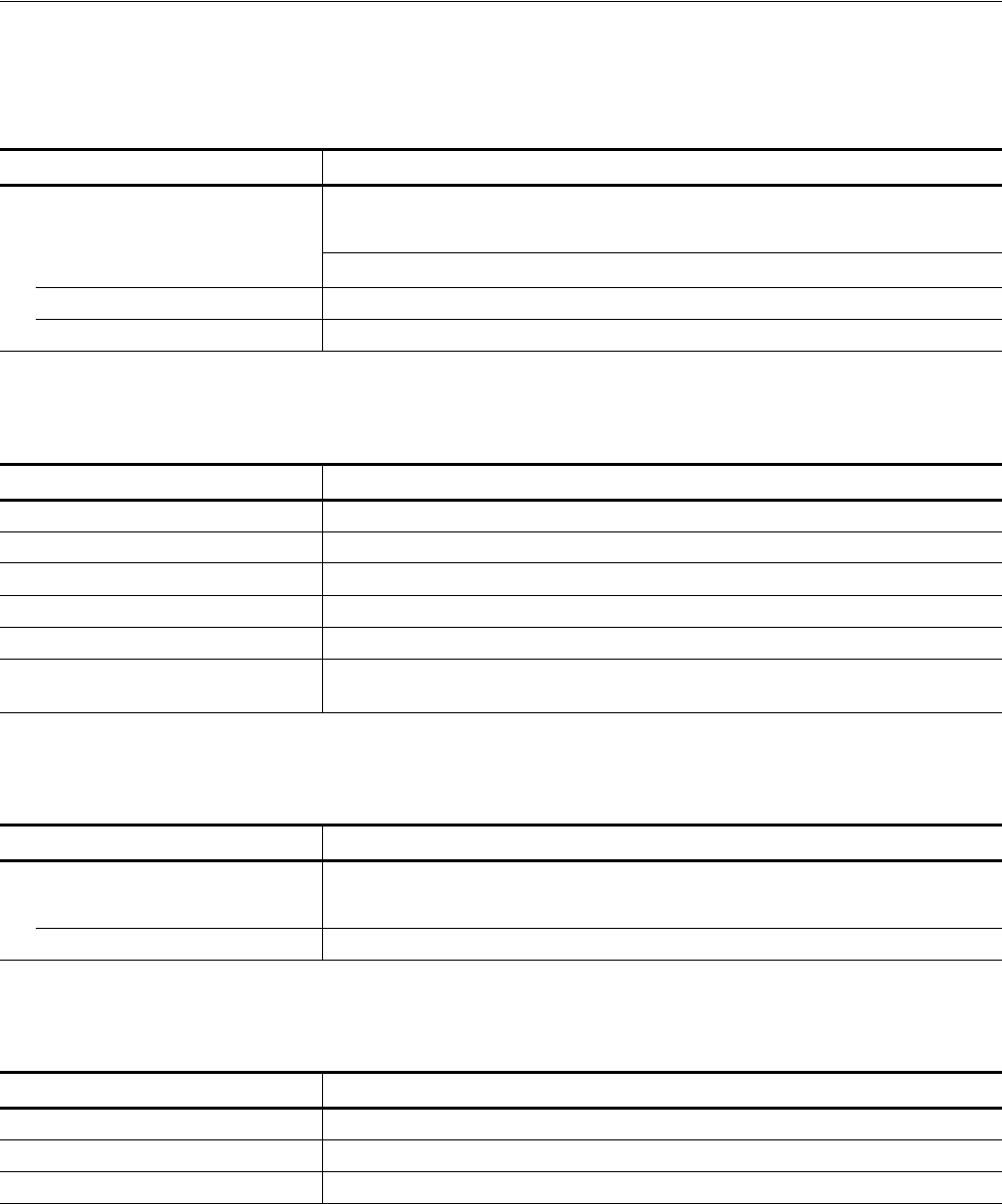
Table A-43: Display
Characteristics Description
Display
Display area Horizontal: 130.6 mm (5.14 in)
Vertical: 97.0 mm (3.81 in)
Resolution 640 (H) × 480 (V) pixels
Size 16 cm (6.4 in.) diag. LCD
Table A-44: AC line power
Characteristics Description
Rating voltage 100 VAC to 240 VAC, CAT II
Voltage range 90 VAC to 250 VAC
Frequency range 48 Hz to 63 Hz
Maximum consumption 220 VA
Maximum current 5 A
Fuse rating 10 A fast, 250 V, UL 198G (3 AG)
5 A (T), 250 V, IEC 127
Table A - 4 5 : Timer
Characteristics Description
Timer
6 yearsOperation time
Type Li 3 V, 190 mAh
Table A-46: Interface connectors
Characteristics Description
GPIB 24–pin, IEEE 488.1 connector on the rear panel
Ethernet 100/10 BASE–T, RJ–45 connector on the rear panel
Keyboard connector 6–pin, mini–DIN connector on the rear panel