
User's Manual


Table Of Contents
- Title page
- Table of Contents
- General Safety Summary
- Preface
- Getting Started
- Operating Basics
- Reference
- Reference
- Menu Structures
- The Setup Menu Screen
- The Graphical Waveform Editor
- The Pattern Editor
- Quick Editing
- The Table Editor
- The Equation Editor
- The Sequence Editor
- The APPL Menu
- The UTILITY Window
- External Keyboards
- Setting General Purpose Knob Direction
- Formatting a Floppy Disk
- Displaying Disk Usage
- Screen Display Enable/Disable
- Focused Color
- Displaying Instrument Status
- Internal Clock (Date and Time)
- Resetting the Instrument
- Connecting to a GPIB Network
- Ethernet Networking
- Hardcopy
- Calibration and Diagnostics
- Upgrading the System Software
- Capturing Waveforms
- Waveform Programming Language
- Command Descriptions
- Programming Examples
- File Conversion
- File Management
- FG Mode
- Waveform Mixing Mode
- Synchronous Operation Mode (AWG710B only)
- Appendices
- Appendix A: Specifications (AWG710B)
- Appendix A: Specifications (AWG710)
- Appendix B: Performance Verification (AWG710B)
- Conventions
- Self Tests
- Performance Tests
- Operating Mode Tests
- Amplitude and Offset Accuracy Tests (Normal Out), (except option 02)
- Amplitude, Offset Accuracy and Rise Time Tests (Direct DA Out), (except option 02)
- Amplitude, Offset Accuracy and Rise Time Tests (for option 02)
- Pulse Response Tests (Normal Out), (except option 02)
- Trigger Input Tests
- Event Input and Enhanced Mode Tests
- External Clock Input and VCO Out Output Tests
- VCO OUT Output Frequency and 10 MHz Reference Input Tests
- Marker Output Tests
- Synchronous Operation Tests
- Appendix B: Performance Verification (AWG710)
- Conventions
- Self Tests
- Performance Tests
- Operating Mode Tests
- Amplitude and Offset Accuracy Tests (Normal Out), (except option 02)
- Amplitude, Offset Accuracy and Rise Time Tests (Direct DA Out), (except option 02)
- Amplitude, Offset Accuracy and Rise Time Tests (for option 02)
- Pulse Response Tests (Normal Out), (except option 02)
- Trigger Input Tests
- Event Input and Enhanced Mode Tests
- 1/4 Clock Frequency and 10 MHz Reference Input Tests
- Marker Output Tests
- Appendix C: Inspection and Cleaning
- Appendix D: Sample Waveforms
- Appendix E: File Transfer Interface Outline
- Appendix F: Miscellaneous
- Appendix G: Sequence File Text Format
- Index
The Equation Editor
3-110 AWG710&AWG710B Arbitrary Waveform Generator User Manual
Starting the Equation Editor
To start the Equation editor, push EDIT (front)!Edit (bottom)!New Equation
(side). You can also automatically start the Equation editor by loading an equation
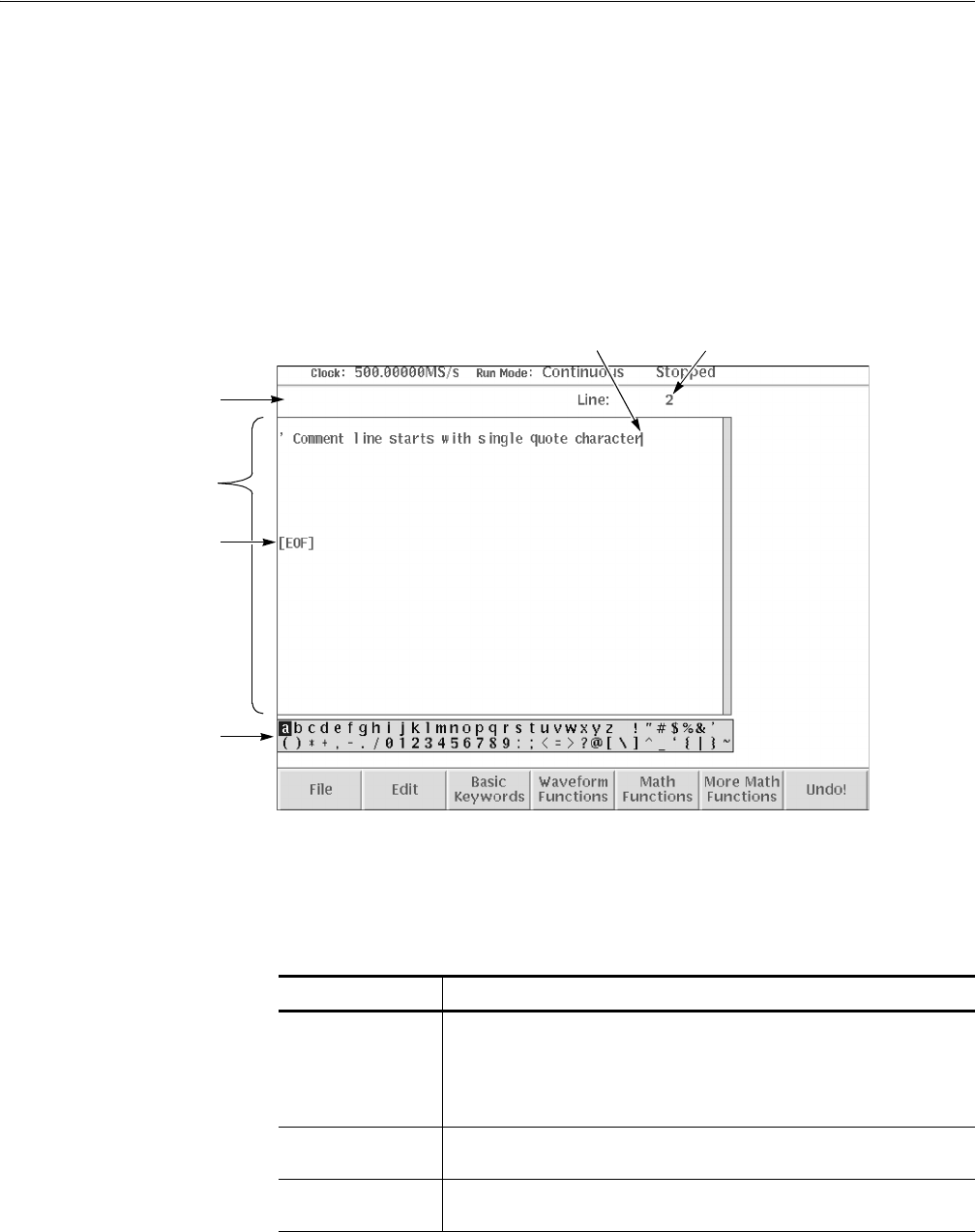
file from the EDIT menu file list. Figure 3-27 shows the Equation editor screen.
Table 3-29 describes the editor screen elements that are specific to the Equation
editor. Table 3-30 describes the bottom menu functions. The sections that follow
Table 3-30 describe the menu operations in detail.
Figure 3-27: Equation editor window
Character pallet
End Of File marker
Tex t e d it
window
File name
Caret Caret line position
Table 3-29: Equation editor screen elements
Element Description
File name The file name to which the equation or text is written, or the name of the file
being edited. The instrument appends the default .txt file extension to all
Equation editor files. If this is a new file, you are prompted to enter a file
name before exiting the editor. It is suggested that you use the .equ file
extension to identify equation files.
Caret line position The line number in the file where the caret is located. The file starts at line
1.
End Of File marker Indicates the end of the file. All equations or text must be entered before
this marker.