
User's Manual


Table Of Contents
- Title page
- Table of Contents
- General Safety Summary
- Preface
- Getting Started
- Operating Basics
- Reference
- Reference
- Menu Structures
- The Setup Menu Screen
- The Graphical Waveform Editor
- The Pattern Editor
- Quick Editing
- The Table Editor
- The Equation Editor
- The Sequence Editor
- The APPL Menu
- The UTILITY Window
- External Keyboards
- Setting General Purpose Knob Direction
- Formatting a Floppy Disk
- Displaying Disk Usage
- Screen Display Enable/Disable
- Focused Color
- Displaying Instrument Status
- Internal Clock (Date and Time)
- Resetting the Instrument
- Connecting to a GPIB Network
- Ethernet Networking
- Hardcopy
- Calibration and Diagnostics
- Upgrading the System Software
- Capturing Waveforms
- Waveform Programming Language
- Command Descriptions
- Programming Examples
- File Conversion
- File Management
- FG Mode
- Waveform Mixing Mode
- Synchronous Operation Mode (AWG710B only)
- Appendices
- Appendix A: Specifications (AWG710B)
- Appendix A: Specifications (AWG710)
- Appendix B: Performance Verification (AWG710B)
- Conventions
- Self Tests
- Performance Tests
- Operating Mode Tests
- Amplitude and Offset Accuracy Tests (Normal Out), (except option 02)
- Amplitude, Offset Accuracy and Rise Time Tests (Direct DA Out), (except option 02)
- Amplitude, Offset Accuracy and Rise Time Tests (for option 02)
- Pulse Response Tests (Normal Out), (except option 02)
- Trigger Input Tests
- Event Input and Enhanced Mode Tests
- External Clock Input and VCO Out Output Tests
- VCO OUT Output Frequency and 10 MHz Reference Input Tests
- Marker Output Tests
- Synchronous Operation Tests
- Appendix B: Performance Verification (AWG710)
- Conventions
- Self Tests
- Performance Tests
- Operating Mode Tests
- Amplitude and Offset Accuracy Tests (Normal Out), (except option 02)
- Amplitude, Offset Accuracy and Rise Time Tests (Direct DA Out), (except option 02)
- Amplitude, Offset Accuracy and Rise Time Tests (for option 02)
- Pulse Response Tests (Normal Out), (except option 02)
- Trigger Input Tests
- Event Input and Enhanced Mode Tests
- 1/4 Clock Frequency and 10 MHz Reference Input Tests
- Marker Output Tests
- Appendix C: Inspection and Cleaning
- Appendix D: Sample Waveforms
- Appendix E: File Transfer Interface Outline
- Appendix F: Miscellaneous
- Appendix G: Sequence File Text Format
- Index
The Pattern Editor
3-92 AWG710&AWG710B Arbitrary Waveform Generator User Manual
Selecting Data Bits to Edit
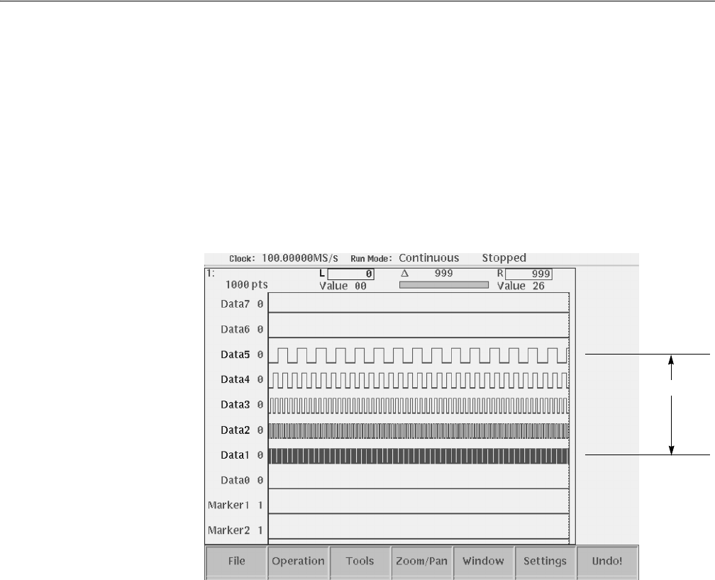
Like the waveform editor, the pattern editor executes operation menu commands
on the data between the two cursors. You must select which of the 8 data bit signals
to edit. Selected bits (data and marker) are indicated by highlighting the data bit
and/or marker names at the left of the pattern display area. The selected bits are
referred to as the edit scope. For example, Figure 3-20 shows the edit scope
(selected data bits) as Data5 through Data1. Note that you can only select
contiguous sets of data bits.
Figure 3-20: Operating data bits (scope)
To specify the edit scope, do the following steps:
1. Push Operation (bottom)!Select Lines (pop–up)!OK (side).
The side menu items From and To appear.
2. Push the From side button and specify the start bit of the scope using the
general purpose knob or numeric buttons.
The option may be Data0 to Data7, Marker1, and Marker2.
3. Push the To side button and specify the end bit of the scope using the general
purpose knob or numeric buttons.
The option may be Data0 to Data7, Marker1, and Marker2.
Scope