
User's Manual


Table Of Contents
- Title page
- Table of Contents
- General Safety Summary
- Preface
- Getting Started
- Operating Basics
- Reference
- Reference
- Menu Structures
- The Setup Menu Screen
- The Graphical Waveform Editor
- The Pattern Editor
- Quick Editing
- The Table Editor
- The Equation Editor
- The Sequence Editor
- The APPL Menu
- The UTILITY Window
- External Keyboards
- Setting General Purpose Knob Direction
- Formatting a Floppy Disk
- Displaying Disk Usage
- Screen Display Enable/Disable
- Focused Color
- Displaying Instrument Status
- Internal Clock (Date and Time)
- Resetting the Instrument
- Connecting to a GPIB Network
- Ethernet Networking
- Hardcopy
- Calibration and Diagnostics
- Upgrading the System Software
- Capturing Waveforms
- Waveform Programming Language
- Command Descriptions
- Programming Examples
- File Conversion
- File Management
- FG Mode
- Waveform Mixing Mode
- Synchronous Operation Mode (AWG710B only)
- Appendices
- Appendix A: Specifications (AWG710B)
- Appendix A: Specifications (AWG710)
- Appendix B: Performance Verification (AWG710B)
- Conventions
- Self Tests
- Performance Tests
- Operating Mode Tests
- Amplitude and Offset Accuracy Tests (Normal Out), (except option 02)
- Amplitude, Offset Accuracy and Rise Time Tests (Direct DA Out), (except option 02)
- Amplitude, Offset Accuracy and Rise Time Tests (for option 02)
- Pulse Response Tests (Normal Out), (except option 02)
- Trigger Input Tests
- Event Input and Enhanced Mode Tests
- External Clock Input and VCO Out Output Tests
- VCO OUT Output Frequency and 10 MHz Reference Input Tests
- Marker Output Tests
- Synchronous Operation Tests
- Appendix B: Performance Verification (AWG710)
- Conventions
- Self Tests
- Performance Tests
- Operating Mode Tests
- Amplitude and Offset Accuracy Tests (Normal Out), (except option 02)
- Amplitude, Offset Accuracy and Rise Time Tests (Direct DA Out), (except option 02)
- Amplitude, Offset Accuracy and Rise Time Tests (for option 02)
- Pulse Response Tests (Normal Out), (except option 02)
- Trigger Input Tests
- Event Input and Enhanced Mode Tests
- 1/4 Clock Frequency and 10 MHz Reference Input Tests
- Marker Output Tests
- Appendix C: Inspection and Cleaning
- Appendix D: Sample Waveforms
- Appendix E: File Transfer Interface Outline
- Appendix F: Miscellaneous
- Appendix G: Sequence File Text Format
- Index
The Graphical Waveform Editor
AWG710&AWG710B Arbitrary Waveform Generator User Manual 3-83
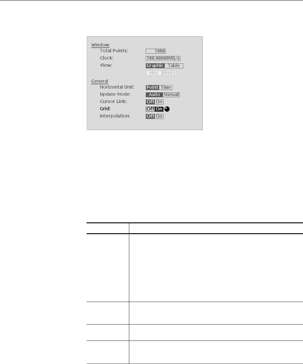
Figure 3-16: Settings dialog box
Window and General are two types of editor setup parameters. Window parameters
only affects the active edit window. General parameters influence all windows
currently opened and that will be opened, whether they are active or not. Table 3-21
describes the Window setup parameters, and Table 3-22 describes the general setup
parameters.
Table 3-21: Setup window parameters
Parameters Descriptions
Total Points Specifies the data length of the waveform in the current window. The default is
1000 points. The range of data points is from 960 to 32400000/64800000
(opt.01) (16200000/32400000 (opt.01) :AWG710)and must be a multiple of 4.
If you specify a value larger than the current data length, one or more zeros are
added at the end of the data. If you specify a value less than the current length,
all data after the end data point is deleted.
The displayed value reflects data point changes resulting from any edit
operations (such as cut or paste) that increase or decrease the number of data
points in the record.
Clock Specifies the clock frequency used to calculate the point–to–point time interval
between each data point. The default setting is 100 MS/s. Note that this clock
does not define the waveform output frequency.
View Selects either the Graphic or Table waveform data display mode. The default
setting is Graphic.
Table Type Specifies to display tabular waveform data in binary or hexadecimal format.
This selection is available only when the View parameter is set to Table. The
Editor displays all data values in real numbers.