
User's Manual


Table Of Contents
- Title page
- Table of Contents
- General Safety Summary
- Preface
- Getting Started
- Operating Basics
- Reference
- Reference
- Menu Structures
- The Setup Menu Screen
- The Graphical Waveform Editor
- The Pattern Editor
- Quick Editing
- The Table Editor
- The Equation Editor
- The Sequence Editor
- The APPL Menu
- The UTILITY Window
- External Keyboards
- Setting General Purpose Knob Direction
- Formatting a Floppy Disk
- Displaying Disk Usage
- Screen Display Enable/Disable
- Focused Color
- Displaying Instrument Status
- Internal Clock (Date and Time)
- Resetting the Instrument
- Connecting to a GPIB Network
- Ethernet Networking
- Hardcopy
- Calibration and Diagnostics
- Upgrading the System Software
- Capturing Waveforms
- Waveform Programming Language
- Command Descriptions
- Programming Examples
- File Conversion
- File Management
- FG Mode
- Waveform Mixing Mode
- Synchronous Operation Mode (AWG710B only)
- Appendices
- Appendix A: Specifications (AWG710B)
- Appendix A: Specifications (AWG710)
- Appendix B: Performance Verification (AWG710B)
- Conventions
- Self Tests
- Performance Tests
- Operating Mode Tests
- Amplitude and Offset Accuracy Tests (Normal Out), (except option 02)
- Amplitude, Offset Accuracy and Rise Time Tests (Direct DA Out), (except option 02)
- Amplitude, Offset Accuracy and Rise Time Tests (for option 02)
- Pulse Response Tests (Normal Out), (except option 02)
- Trigger Input Tests
- Event Input and Enhanced Mode Tests
- External Clock Input and VCO Out Output Tests
- VCO OUT Output Frequency and 10 MHz Reference Input Tests
- Marker Output Tests
- Synchronous Operation Tests
- Appendix B: Performance Verification (AWG710)
- Conventions
- Self Tests
- Performance Tests
- Operating Mode Tests
- Amplitude and Offset Accuracy Tests (Normal Out), (except option 02)
- Amplitude, Offset Accuracy and Rise Time Tests (Direct DA Out), (except option 02)
- Amplitude, Offset Accuracy and Rise Time Tests (for option 02)
- Pulse Response Tests (Normal Out), (except option 02)
- Trigger Input Tests
- Event Input and Enhanced Mode Tests
- 1/4 Clock Frequency and 10 MHz Reference Input Tests
- Marker Output Tests
- Appendix C: Inspection and Cleaning
- Appendix D: Sample Waveforms
- Appendix E: File Transfer Interface Outline
- Appendix F: Miscellaneous
- Appendix G: Sequence File Text Format
- Index
The Graphical Waveform Editor
3-78 AWG710&AWG710B Arbitrary Waveform Generator User Manual
Digital Filter...
The Digital Filter... command applies a digital filter to the whole of the active
window’s waveform and displays the result in another window. If three windows
are open, the operation will not work.
The digital filter implemented in this instrument is composed of n FIR filter and
Kaizer window functions, where n represents the number of delay elements that
composes the filter. You can specify the n as a tap that varies from 3 to 101. The
larger the value of n (number of taps), the greater the filtering capability. However,
filtering will take a longer time to perform as the value of n increases.
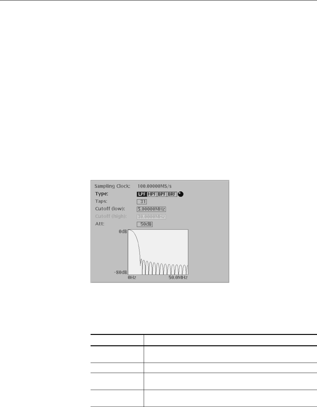
Digital Filter Dialog Box. Figure 3-14 shows the Digital Filter dialog box. Table
3-17 describes the digital filter parameters.
Applying the digital filter results in delay by (number of taps - 1)/2. The original
data is regarded as an iterative waveform during calculation. As a result of the
delay due to the filter, the portion around the start of the output waveform is
influenced by the end of the input waveform.
Figure 3-14: Digital Filter dialog box
Table 3-17: Digital filter dialog box parameters
Parameters Descriptions
Type Selects the filter type. You can select LPF (low pass filter), HPF (high pass
filter), BPF (band pass filter), or BRF (band rejection filter).
Taps Specifies the number of taps (odd number, 3 to 101).
Cutoff Specifies the cutoff frequency. If you selected BPF or BRF, you must
specify the upper and lower bandpass limits.
Att Specifies the attenuation of the inhibited bands (21 to 100, in dB
increments).