
User's Manual


Table Of Contents
- Title page
- Table of Contents
- General Safety Summary
- Preface
- Getting Started
- Operating Basics
- Reference
- Reference
- Menu Structures
- The Setup Menu Screen
- The Graphical Waveform Editor
- The Pattern Editor
- Quick Editing
- The Table Editor
- The Equation Editor
- The Sequence Editor
- The APPL Menu
- The UTILITY Window
- External Keyboards
- Setting General Purpose Knob Direction
- Formatting a Floppy Disk
- Displaying Disk Usage
- Screen Display Enable/Disable
- Focused Color
- Displaying Instrument Status
- Internal Clock (Date and Time)
- Resetting the Instrument
- Connecting to a GPIB Network
- Ethernet Networking
- Hardcopy
- Calibration and Diagnostics
- Upgrading the System Software
- Capturing Waveforms
- Waveform Programming Language
- Command Descriptions
- Programming Examples
- File Conversion
- File Management
- FG Mode
- Waveform Mixing Mode
- Synchronous Operation Mode (AWG710B only)
- Appendices
- Appendix A: Specifications (AWG710B)
- Appendix A: Specifications (AWG710)
- Appendix B: Performance Verification (AWG710B)
- Conventions
- Self Tests
- Performance Tests
- Operating Mode Tests
- Amplitude and Offset Accuracy Tests (Normal Out), (except option 02)
- Amplitude, Offset Accuracy and Rise Time Tests (Direct DA Out), (except option 02)
- Amplitude, Offset Accuracy and Rise Time Tests (for option 02)
- Pulse Response Tests (Normal Out), (except option 02)
- Trigger Input Tests
- Event Input and Enhanced Mode Tests
- External Clock Input and VCO Out Output Tests
- VCO OUT Output Frequency and 10 MHz Reference Input Tests
- Marker Output Tests
- Synchronous Operation Tests
- Appendix B: Performance Verification (AWG710)
- Conventions
- Self Tests
- Performance Tests
- Operating Mode Tests
- Amplitude and Offset Accuracy Tests (Normal Out), (except option 02)
- Amplitude, Offset Accuracy and Rise Time Tests (Direct DA Out), (except option 02)
- Amplitude, Offset Accuracy and Rise Time Tests (for option 02)
- Pulse Response Tests (Normal Out), (except option 02)
- Trigger Input Tests
- Event Input and Enhanced Mode Tests
- 1/4 Clock Frequency and 10 MHz Reference Input Tests
- Marker Output Tests
- Appendix C: Inspection and Cleaning
- Appendix D: Sample Waveforms
- Appendix E: File Transfer Interface Outline
- Appendix F: Miscellaneous
- Appendix G: Sequence File Text Format
- Index
The Setup Menu Screen
3-42 AWG710&AWG710B Arbitrary Waveform Generator User Manual
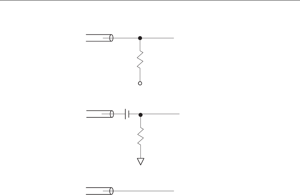
(1) 50Ω terminated to VBB (-1.3V)
(2) 50Ω terminated with AC coupling
(3) Not terminated (High impedance)
Figure 3-4: 1/4 CLOCK OUT connection examples
Clock Ref
This button lets you set the instrument clock source. You can specify the internal
clock generator or an external 10 MHz clock signal connected to the rear panel 10
MHz REF IN connector. The acceptable external clock signal is
10 MHz ± 0.1 MHz, 0.2 V
p–p
to 3.0 V
p–p
.
The instrument synchronizes the internal sample clock phase–lock–loop (PLL)
generator to the external clock. Using an external sample clock can help you
synchronize the AWG710&AWG710B Arbitrary Waveform Generator with the
rest of your test equipment.
If you use the external clock as the reference clock, you can change the output
waveform clock rate like the internal clock.
Use the following procedure to select the reference clock source:
1. Push SETUP (front)!Horizontal (bottom)!Clock Ref (side).
2. Push the Clock Ref side button to toggle between Internal and External.
50 Ω
50 Ω
–1.3 V
50 Ω
50 Ω
50 Ω