
User's Manual


Table Of Contents
- Title page
- Table of Contents
- General Safety Summary
- Preface
- Getting Started
- Operating Basics
- Reference
- Reference
- Menu Structures
- The Setup Menu Screen
- The Graphical Waveform Editor
- The Pattern Editor
- Quick Editing
- The Table Editor
- The Equation Editor
- The Sequence Editor
- The APPL Menu
- The UTILITY Window
- External Keyboards
- Setting General Purpose Knob Direction
- Formatting a Floppy Disk
- Displaying Disk Usage
- Screen Display Enable/Disable
- Focused Color
- Displaying Instrument Status
- Internal Clock (Date and Time)
- Resetting the Instrument
- Connecting to a GPIB Network
- Ethernet Networking
- Hardcopy
- Calibration and Diagnostics
- Upgrading the System Software
- Capturing Waveforms
- Waveform Programming Language
- Command Descriptions
- Programming Examples
- File Conversion
- File Management
- FG Mode
- Waveform Mixing Mode
- Synchronous Operation Mode (AWG710B only)
- Appendices
- Appendix A: Specifications (AWG710B)
- Appendix A: Specifications (AWG710)
- Appendix B: Performance Verification (AWG710B)
- Conventions
- Self Tests
- Performance Tests
- Operating Mode Tests
- Amplitude and Offset Accuracy Tests (Normal Out), (except option 02)
- Amplitude, Offset Accuracy and Rise Time Tests (Direct DA Out), (except option 02)
- Amplitude, Offset Accuracy and Rise Time Tests (for option 02)
- Pulse Response Tests (Normal Out), (except option 02)
- Trigger Input Tests
- Event Input and Enhanced Mode Tests
- External Clock Input and VCO Out Output Tests
- VCO OUT Output Frequency and 10 MHz Reference Input Tests
- Marker Output Tests
- Synchronous Operation Tests
- Appendix B: Performance Verification (AWG710)
- Conventions
- Self Tests
- Performance Tests
- Operating Mode Tests
- Amplitude and Offset Accuracy Tests (Normal Out), (except option 02)
- Amplitude, Offset Accuracy and Rise Time Tests (Direct DA Out), (except option 02)
- Amplitude, Offset Accuracy and Rise Time Tests (for option 02)
- Pulse Response Tests (Normal Out), (except option 02)
- Trigger Input Tests
- Event Input and Enhanced Mode Tests
- 1/4 Clock Frequency and 10 MHz Reference Input Tests
- Marker Output Tests
- Appendix C: Inspection and Cleaning
- Appendix D: Sample Waveforms
- Appendix E: File Transfer Interface Outline
- Appendix F: Miscellaneous
- Appendix G: Sequence File Text Format
- Index
Menu Structures
3-8 AWG710&AWG710B Arbitrary Waveform Generator User Manual
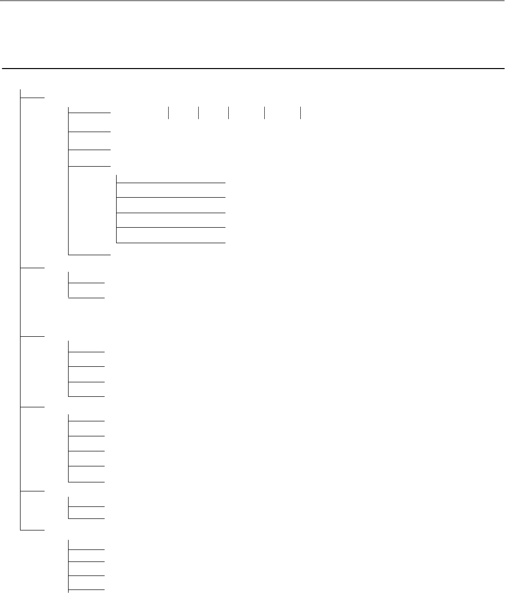
Saves/restores current settings
Save/Restore
Main
menu
Bottom
menu
Side
menu
Subbottom
menu
Subside
menu
Pop-up or
dialog menu
Description
SETUP (cont.)
Ver tic al
Note: Use the General Purpose Knob to select.
Filter {Through
Amplitude (0.02 V
p-p
to 2.000V
p-p
), (option 02: 0.5 V
p-p
to 1.000V
p-p
)
Offset (-0.5 V to +0.5V), (except option 02)
Marker...
Marker 1 High Level (-1.00 to 2.45 V (-1.1 to 3.0V :AWG710))
Marker 1 Low Level (-2.00 to 2.40 V (-1.1 to 3.0V :AWG710))
Marker 2 High Level (-1.00 to 2.45 V (-1.1 to 3.0V :AWG710))
Marker 2 Low Level (-2.00 to 2.40 V (-1.1 to 3.0V :AWG710))
Previous menu
Output {Normal | Direct}, (except option 02)
Horizontal
Clock (50 kS/s to 4.2 GS/s (50 kS/s to 4.0 GS/s : AWG710))
Clock Ref {Internal | External}
Adjusts vertical axis paramet
e
Run Mode
Save Setup
Restore Setup
Interval (1.0 µs to 10.0s)
Source {External | Internal}
Slope (or Polarity) {Positive | Negative}
Level (-5.0 to 5.0 V)
Impedance {50 Ω | 1 kΩ }
Continuous
Triggered
Gated
Enhanced
Adjusts horizontal parameters
Selects run mode
the Front Panel Edit button repeatedly to return to the Edit Main menu.
Sets trigger parametersTrigger
20 MHz 50 MHz 100 MHz 200 MHz Through}, (except option 02)
Extend Operation
FG...
Waveform Mixing
Sync - Master
Sync - Slave
Clock Src {Internal | External} (AWG710B only)