
Spectrum Monitor Instruction Manual

Operating Instructions
1705A Spectrum Monitor
2-5
70 MHz
SPECTRUM MONITOR
333--3990 --01
INPUT
BESCHLEUNIGUNGSSPANNUNG KLEINER ALS
20kV
DIE IN DIESEM GERA T ENTSTEHENDE
RONTGENSTRAHLUNG I ST AUSREICHEND ABGESCHIRMT
1
2
3
4
6
5
WARNING
TO AVOID ELECTRI CAL SHOCK, THE POWER
CORD PROTECTIVE GROUNDING CONDUCTOR
MUST BE CONNECTED TO EARTH GROUND.
0.7A MAX
50/60Hz
90-250V
REPLACE FUSE ONLY WITH
250V 2A F TYPE
L BAND
INPUT
!
LNB POW-
ER
ON
!
LNB POW-
ER
OFF
+18 VDC @ 250 mA
ON
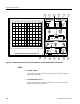
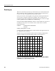
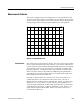
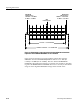
Figure 2-2: 1705A rear panel controls and connectors; refer to text for descriptions
of controls identified with circled numbers
3. LNB POWER (Indicator)
LED indicator that lights when the +18 V supply is turned on and operating
correctly. Indicator will not light if the +18 V supply is shorted.
4. 70 MHz
A75Ω input bnc-type connector used for the input of the 45 -- 100 MHz rf.
5. AC FUSE
Holder for the instrument’s mains fuse.
6. AC POWER
A standard ac plug receptacle for 120 or 220 Vac power mains.
POWER