
Spectrum Monitor Instruction Manual


Maintenance
6-26
1705A Spectrum Monitor
FRONT
J1
J3
J2 J4
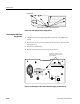
Ground strap
Remove these screws to remove this board
Figure 6-12: Removing the Power Supply board
1. Unplug the interconnecting plug from the right side of the LNB power
supply.
2. Remove the two Torx screws securing the circuit board to the rear panel.
See Figure 6-13.
3. Remove the circuit board.
4. Replace the circuit board by reversing the procedure.
BESCHLEUNIGUNGSSPANNUNG KLEINER ALS20kV
DIE IN DIESEM GERA T ENTSTEHENDE
RONTGENSTRAHLUNG I ST AUSREICHEND ABGESCHIRMT
TO AVOID ELECTRI CAL SHOCK, THE POWER
CORD PROTECTIVE GROUNDING CONDUCTOR
MUST BE CONNECTED TO EARTH GROUND.
SPECTRUM MONITOR
70 MHz
INPUT
L-BAND
INPUT
LNB POWER
LNB POWER
ON
OFF
+18VDC@250mA
ON
WARNING
0.70 MAX
50/60Hz
90 - 250V
REPLACE FUSE ONLY
WITH
250V 2A F TYPE
333-- 3990--01
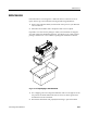
Remove these screws to remove
LNB Power Supply board (A4) or to
replace LNB LED.
Figure 6-13: Mounting screws for the LNB Power Supply circuit board, A4
Removing the LNB Power
Supply Board