
Spectrum Monitor Instruction Manual


Checks and Adjustments
1705A Spectrum Monitor
5-5
s. CHECK -- that the readout still reads 1000, ±10.
u. CHECK -- that the marker is on screen.
v. CHECK -- that the readout still reads 1000, ±10.
x. CHECK -- that the marker is on screen.
12. Check L--Band Gain and Flatness
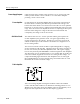
e. CHECK -- that the marker is on the same crt center line (vertically),
±0.5 Division.
g. CHECK -- that the marker is on the same crt line (vertically), ±0.5
Division.
j. CHECK -- that the marker tip is on the --10 reference line, ±0.5
Division. Note: Make sure that the baseline is on the --70 graticule
reference line.
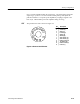
13. Check Positioning Range
b. CHECK -- that the tip can be positioned 2 Divisions left and right of
center.
e. CHECK -- that the marker tip can be positioned 3 Divisions down from
its present position.
f. CHECK -- that the baseline can be positioned to the --30 graticule line.
14. Check2dB/DivGain
g. CHECK -- for more than 1 Division of amplitude change.
h. CHECK -- that the noise floor can be positioned on screen.
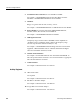
1. Preliminary S etup
a. Connect the 1705A ac power cord to the variable autotransformer. Turn
power on and set the autotransformer to the local nominal mains voltage
(110 V or 220 V). Allow 15 minutes for warm-up time before continu-
ing.
b. Set up the 1705A as shown in Table 5--1.
Long Form Procedure
Test Equipment Depot - 800.517.8431 - 99 Washington Street Melrose, MA 02176 - FAX 781.665.0780 - TestEquipmentDepot.com