Instruction Manual 1705A Spectrum Monitor (SN B040000 and Above) 070-8222-08 Warning The servicing instructions are for use by qualified personnel only. To avoid personal injury, do not perform any servicing unless you are qualified to do so. Refer to all safety summaries prior to performing service. www.tektronix.com Test Equipment Depot - 800.517.8431 - 99 Washington Street Melrose, MA 02176 - FAX 781.665.0780 - TestEquipmentDepot.
Table of Contents General Safety Summary . . . . . . . . . . . . . . . . . . . . . . . . . . . . . . . . . . . . . . . . . . . . . . Service Safety Summary . . . . . . . . . . . . . . . . . . . . . . . . . . . . . . . . . . . . . . . . . . . . . . Preface . . . . . . . . . . . . . . . . . . . . . . . . . . . . . . . . . . . . . . . . . . . . . . . . . . . . . . . . . . . . . Contacting Tektronix ix xi xiii xv Introduction Section 1 Introduction . . . . . . . . . . . . . . . . . . . . . . . . . . . . . . .
Table of Contents Vertical Scales . . . . . . . . . . . . . . . . . . . . . . . . . . . . . . . . . . . . . . . . . . . . . . . . . . . . . . Horizontal Scales . . . . . . . . . . . . . . . . . . . . . . . . . . . . . . . . . . . . . . . . . . . . . . . . . . . . Center Frequency Readout . . . . . . . . . . . . . . . . . . . . . . . . . . . . . . . . . . . . . . . . . . . . . . . . Customizing Frequency Readout . . . . . . . . . . . . . . . . . . . . . . . . . . . . . . . . . . . . . . . . . . .
Table of Contents Ramp Generator . . . . . . . . . . . . . . . . . . . . . . . . . . . . . . . . . . . . . . . . . . . . . . . . . . . . . Gain Control (SPAN/DIV) . . . . . . . . . . . . . . . . . . . . . . . . . . . . . . . . . . . . . . . . . . . . . Sweep Shapers . . . . . . . . . . . . . . . . . . . . . . . . . . . . . . . . . . . . . . . . . . . . . . . . . . . . . . Bright-- Up Generator . . . . . . . . . . . . . . . . . . . . . . . . . . . . . . . . . . . . . . . . . . . . . . . . .
Table of Contents Short-- Form Procedure . . . . . . . . . . . . . . . . . . . . . . . . . . . . . . . . . . . . . . . . . . . . . . . . Long Form Procedure . . . . . . . . . . . . . . . . . . . . . . . . . . . . . . . . . . . . . . . . . . . . . . . . 5-- 17 5-- 18 Maintenance . . . . . . . . . . . . . . . . . . . . . . . . . . . . . . . . . . . . . . . . . . 6- - 1 Section 6 Maintenance . . . . . . . . . . . . . . . . . . . . . . . . . . . . . . . . . . . . . . . . . . . . . . . .
Table of Contents Replaceable Electrical Parts Section 8 Replaceable Electrical Parts . . . . . . . . . . . . . . . . . . . . . . . . . . . . . . . . . . . 8--1 Parts Ordering Information . . . . . . . . . . . . . . . . . . . . . . . . . . . . . . . . . . . . . . . . . . . . . . . . Using the Replaceable Electrical Parts List . . . . . . . . . . . . . . . . . . . . . . . . . . . . . . . . . . . Cross Index-- Mfr. Code Number to Manufacturer . . . . . . . . . . . . . . . . . . . . . . . . . . .
Table of Contents List of Figures Figure 1-1: 1705A used to locate satellites and determine maximum signal level . . . . . . . . . Figure 1-2: Relationship of a communications satellite to earth . . . . . . . . . . . . . . . . . . . . . . . Figure 1-3: Angle A (the difference at a specific latitude between the angle to the sun and the angle to a satellite) . . . . . . . . . . . . . . . . . . . . . . . . . . . . . . . . . . . . . . . . . Figure 1-4: Sample longitudinal map of the Ku-Band satellites . . . .
Table of Contents Figure 3-8: Considerations for custom installation of an instrument . . . . . . . . . . . . . . . . . . . . 3--8 Figure 4-1: 1705A L--Band comb display showing the areas each of the six sweep shaper variable resistors adjust . . . . . . . . . . . . . . . . . . . . . . . . . . . . . . . . . . . . . . . . . . . . . Figure 4-2: Output duty cycle of the pulse width modulator used in the +18 V Power Supply Figure 4-3: Pinout of the CRT Socket . . . . . . . . . . . . . . . . . . . . . . . . .
Table of Contents List of Tables viii Table 1--1: Spectrum Display . . . . . . . . . . . . . . . . . . . . . . . . . . . . . . . . . . . . . . . . . . . . . . . . . Table 1--2: CRT Display . . . . . . . . . . . . . . . . . . . . . . . . . . . . . . . . . . . . . . . . . . . . . . . . . . . . . Table 1--3: Power Source . . . . . . . . . . . . . . . . . . . . . . . . . . . . . . . . . . . . . . . . . . . . . . . . . . . . Table 1--4: Environmental Characteristics . . . . . . . . . . . . . . . . . . . . . .
General Safety Summary Review the following safety precautions to avoid injury and prevent damage to this product or any products connected to it. To avoid potential hazards, use this product only as specified. Only qualified personnel should perform service procedures. While using this product, you may need to access other parts of the system. Read the General Safety Summary in other system manuals for warnings and cautions related to operating the system.
General Safety Summary Provide Proper Ventilation. Refer to the manual’s installation instructions for details on installing the product so it has proper ventilation. Symbols and Terms Terms in this Manual. These terms may appear in this manual: WARNING. Warning statements identify conditions or practices that could result in injury or loss of life. CAUTION. Caution statements identify conditions or practices that could result in damage to this product or other property. Terms on the Product.
Service Safety Summary Only qualified personnel should perform service procedures. Read this Service Safety Summary and the General Safety Summary before performing any service procedures. Do Not Service Alone. Do not perform internal service or adjustments of this product unless another person capable of rendering first aid and resuscitation is present. Disconnect Power. To avoid electric shock, switch off the instrument power, then disconnect the power cord from the mains power.
Service Safety Summary xii 1705A Spectrum Monitor
Preface The information in this manual is intended for instrument operators and service technicians. Operators are assumed to befamiliar with basic television terms and measurements. Qualified service technicians are also assumed to be familiar with television terms and measurements, and have moderate experience with analog and logic circuits. The manual is divided into two parts: Operator’s Information and Service Information. The Operator’s Information is useful to both operators and service technicians.
Preface Section 7, Options Section 8, Replaceable Electrical Parts Section 9, Diagrams Section 10, Replaceable Mechanical Parts xiv Section 7, Options, documents instrument options. The information in this section summarizes the options. Additional details are included in appro-priate places throughout the manual. Section 8, Replaceable Electrical Parts, includes order information and part numbers for all replaceable electrical parts. Section 9, Diagrams, contains servicing illustra-tions.
Preface Contacting Tektronix Phone 1-800-833-9200* Address Tektronix, Inc. Department or name (if known) 14200 SW Karl Braun Drive P.O. Box 500 Beaverton, OR 97077 USA Web site www.tektronix.com Sales support 1-800-833-9200, select option 1* Service support 1-800-833-9200, select option 2* Technical support Email: techsupport@tektronix.com 1-800-833-9200, select option 3* 6:00 a.m. - 5:00 p.m. Pacific time * 1705A Spectrum Monitor This phone number is toll free in North America.
Preface xvi 1705A Spectrum Monitor
Introduction
Section 1 Introduction The TEKTRONIX 1705A Spectrum Monitor is an 8½” wide by 5¼” high special purpose spectrum analyzer. It weighs approximately 8½ pounds and is powered from an ac source. The crt occupies approximately two-thirds of the front-panel area, with the control panel taking up the remainder of the space. Operation is controlled by a microprocessor that polls the front-panel switches. Front-panel switches are of the momentary touch type with lighted functional indicators.
Introduction LOW-NOISE AMPLIFIER/ BLOCK DOWN CONVERTER 1705A SPECTRUM MONITOR RECEIVER Figure 1-1: 1705A used to locate satellites and determine maximum signal level Options The only options currently available for the 1705A Spectrum Monitor are the power plug options described in Section 7 (Options). If no power cord options are ordered, instruments are shipped with the North American 125 V power cord and one replacement fuse.
Introduction Optional Accessories Camera, C9 (Option 20) Viewing Hood (016-0475-00) Front Panel Cover (200-3897-01) 1700F00, Plain Cabinet (painted silver grey) 1700F02, Portable Cabinet (painted silver grey with handle, feet, and front cover) 1700F05, Side-by-Side Rack Adapter 1700F06, Blank Half-Rack Width Panel 1700F07, Utility Drawer Safety Information The 1705A Spectrum Monitor is intended to operate from an ac power source that will not apply more than 250 V rms between the supply conductors or bet
Introduction ELECTRICAL SPECIFICATION Table 1- 1: Spectrum Display Characteristic Frequency Range L---Band 70 MHz Performance Requirements 950 to 1800 MHz 45 to 100 MHz Frequency Span L---Band Full 10 MHz/Division 1 MHz/Division 100 kHz/Division F---type connector Bnc connector 10 Horiz. Div. Equals: 1000 MHz 100 MHz 10 MHz 1 MHz 11 10 Horiz. Div. Equals: 50 MHz 10 MHz 1 MHz 5 Typically 0.5 minor Division.
Introduction Table 1- 1: Spectrum Display (Cont.) Characteristic Performance Requirements Frequency Bright Up Marker Registration Readout Accuracy Full Span has bright up and frequency readout (without cursor). Bright-up area will be on screen in at least the next narrower span. L---Band ±20 MHz. 70 MHz ±2 MHz Resolution 6 dB Down 300 kHz 10 kHz Check Step Supplemental Information 5 Typically ±10 MHz. Typically ±1 MHz. 11 5 300 kHz ±1 Division at 100 kHz Span/Div.
Introduction Table 1- 4: Environmental Characteristics Characteristic Supplemental Information Temperature Non-Operating Operating ---55˚C to +75˚C. 0˚C to +50˚C. Altitude Non-Operating Operating To 50,000 feet (15,000 meters). To 15,000 feet (4,800 meters). Vibration --- Operating 15 minutes each axis at 0.015”, frequency varied from 10---55---10 Hz in 1-minute cycles with instrument secured to vibration platform.
Introduction Table 1- 6: Certifications and Compliances (cont.) FCC Compliance Emissions comply with FCC Code of Federal Regulations 47, Part 15, Subpart B, Class A Limits Installation (Overvoltage) Category Terminals on this product may have different installation (overvoltage) category designations. The installation categories are: Pollution Degree CAT III Distribution-level mains (usually permanently connected). Equipment at this level is typically in a fixed industrial location.
Introduction Table 1- 6: Certifications and Compliances (cont.) Safety Certification Compliance Temperature, operating +5 to +40_ C Altitude (maximum operating) 2000 meters 1- 8 Equipment Type Test and measuring Safety Class Class 1 (as defined in IEC 1010-1, Annex H) - grounded product Overvoltage Category Overvoltage Category II (as defined in IEC 1010-1, Annex J) Pollution Degree Pollution Degree 2 (as defined in IEC 1010-1). Note: Rated for indoor use only.
Introduction APPLICATIONS The principal application for the TEKTRONIX 1705A Spectrum Monitor is to provide a convenient method to locate and identify Ku-Band satellites, find the correct transponder and check on its availability, and optimize antenna positioning and polarization. The remainder of this section provides basic satellite communications application data. Specific operating instructions are located in Section 2, Operating Instructions.
Introduction orbit of the satellite. If the orbit of an equatorial orbiting satellite were roughly equal to the distance from earth to the sun, ordinary latitude could be used to determine the elevation of the antenna, which is, of necessity, very finely focused. However since there is a disparity this angle is somewhat less than the latitude for the earth station. See Figure 1-3. Simple logic readily points out that as the latitude increases the angle from horizon to the satellite decreases.
Introduction RCA K2 81° SPACENET 2 69° SBS 3 97° GSTAR A2 103° GSTAR A1 105° ANIK B 109° MORELOS 1 113.5° SPACENET 1 120° RCA K1 85° ANIK C2 112.5° MORELOS 2 116.
Introduction L- Band Input Signals At the present time there are numerous satellites in geostationary orbit. The transponders on each have specific assigned functions, which makes it essential to accomplish at least four things before illuminating a particular transponder: 1. Locate a satellite. 2. Identify the satellite. 3. Find the transponder and check availability with the satellite operator. 4. Optimize signal strength and polarization.
Introduction Zeroing in on a Satellite In almost all cases a set procedure for Locating, Identifying, Finding (transponders), and Optimizing will be followed. The 1705A Spectrum Monitor is a tool that greatly simplifies the individual steps so the correct satellite transponder can be accessed in the minimum time.
Introduction Tek 12.20 GHZ REF - 10 - 20 - 30 - 40 - 50 - 60 - 70 +f L O G Figure 1-6: A computer representation of the 1705A display showing the 12.198 GHz horizontally polarized telemetry beacon on the SATCOM K2 satellite (Span/Div set to 100 kHz with a 10 kHz Resolution filter) Transponder Polarization. Whether one or two polarizations are used can often be an easy way to identify a satellite.
Introduction TRANSPONDER FREQUENCY AND NUMBER TRANSPONDER NUMBER DOWN LINK FREQUENCY 11.729GHz 11.788GHz 1 11.847GHz 11.906GHz 11.965GHz 12.024GHz 12.083GHz 12.142GHz 5 7 9 11 13 15 3 2 4 6 8 10 12 14 16 11.7585GHz 11.8175GHz 11.8765GHz 11.9355GHz 11.9945GHz 12.0535GHz 12.1125GHz 12.
Introduction 11.73 GHZ Tek REF - 10 - 20 - 30 - 40 - 50 - 60 1 3 5 7 9 11 13 15 - 70 +f L O G Figure 1-8: Simulation of a 1705A FULL SPAN/DIV display showing six transponders illuminated Looking at Exciters with the 70 MHz Input The 70 MHz Input to the spectrum monitor is a bnc connector. It is designed for use with the IF signal from an up link exciter.
Introduction HPA RF OUT IN UP CONVERTER OUT IN 70 MHZ INPUT 1705A SPECTRUM MONITOR DIRECTIONAL COUPLER OUT VIDEO EXCITER Figure 1-9: Up link Video Exciter, Up converter, and High Power Amplifier (HPA) showing how to hook up a 1705A Spectrum Monitor to look at the Video Exciter output In addition to the other measurements that can be made a quick check of HPA, antenna, and transponder (as a system) can be made by comparing the exciter output (using the 70 MHz input) to the incoming signal from the do
Introduction LNB L-OUT Ku-IN Ku-BAND 12 GHZ Ku-BAND 14 GHZ HPA RF OUT IN L-BAND 900--1450 MHZ UP CONVERTER 1705A SPECTRUM MONITOR 3 dB SPLITTER OUT IN 70 MHZ INPUT DIRECTIONAL COUPLER OUT VIDEO EXCITER RECEIVER Figure 1-10: 1705A hooked up to look at either the output of the Video Exciter (70 MHz) or the Receiver Input (L-Band) 1- 18 1705A Spectrum Monitor
Operating Instructions
Section 2 Operating Instructions These instructions provide information about the front-panel controls and indicators, rear-panel connectors and switch, powering-up, and the measurement graticule and alphanumeric readout. Front-panel Controls and Indicators The front--panel controls and indicators consist of momentary contact push-button switches, with backlit switch selections, and variable controls. For frontpanel control and indicator locations, see Figure 2-1.
Operating Instructions 4 1 2 Tektronix 1705A MONITOR SPECTRUM FILTER REF Tek INPUT VIDEO RESOLUTION ON 300 KHz LBAND 10 KHz 70 MHz - 10 - 20 5 3 6 SWEEP SPEED CENTER FREQUENCY - 30 - 40 SPAN/DIV MENU - 50 100 KHz - 60 +f L O G 10 MHz FULL DISPLAY FOCUS - 70 1 MHz SCALE INTENS TRACE ROTATION POWER POSITION HORIZONTAL VERTICAL ON = HOLD FOR FUNCTION 7 11 10 8 12 13 9 Figure 2-1: 1705A front panel; refer to text for descriptions of controls identified with cir
Operating Instructions 6. SPAN/DIV Two push-button switches (left and right) that select the calibrated span per division. Each span is indicated by a front-panel LED. FULL -- Provides a span of 50 MHz per division for the L--Band (900 -- 2000 MHz) input, and 5 MHz per division (45 to 100 MHz) for the 70 MHz input. 10 MHz -- Sets display span to 10 MHz per division. Displays a maximum of 120 MHz for one full sweep (not available for the 70 MHz input).
Operating Instructions POSITION 11. HORIZONTAL A variable control that positions the trace horizontally (X axis). 12. VERTICAL A variable control that positions the display vertically (Y axis). POWER 13. POWER Switches the instrument between a powered up state and standby. Portions of the Power Supply circuit board have mains potential on them in either state. A mechanical indicator in the center of the switch shows the status of the POWER switch. WARNING.
Operating Instructions 6 333-- 3990-- 01 SPECTRUM MONITOR DIE IN DIESEM GERAT ENTSTEHENDE RONTGENSTRAHLUNG IST AUSREICHEND ABGESCHIRMT 20kV BESCHLEUNIGUNGSSPANNUNG KLEINER ALS WARNING TO AVOID ELECTRICAL SHOCK, THE POWER CORD PROTECTIVE GROUNDING CONDUCTOR MUST BE CONNECTED TO EARTH GROUND. 0.
Operating Instructions Powering- up When the 1705A is first powered up, it should come up in a measurement mode. Most commonly it will be configured as it was when it was last turned off. If not, there are some very simple checks that should be made. If the power switch is showing ON, but the graticule and front-panel indicators do not come on, check for a mains power problem, such as a blown fuse or interrupted power mains (unplugged or main breaker thrown).
Operating Instructions Measurement Graticule The 1705A is equipped with an internal graticule crt. The graticule has an 8 X 10 division scale that is lighted. Scale brilliance is controlled by the front-panel SCALE control. Figure 2-4 shows the 1705A graticule. Refer to this figure and subsequent figures when reading the following discussion of the graticule.
Operating Instructions Table 2- 1: dB Reference Reading in dB Voltage Ratio Power Ratio Reading in dB Voltage Ratio Power Ratio 0.0 0.1 0.2 0.3 1.000 1.012 1.023 1.035 1.000 1.023 1.047 1.072 25.0 26.0 27.0 28.0 17.783 19.953 22.387 25.119 316.228 398.107 501.187 630.957 0.4 1.047 1.096 29.0 28.184 794.328 0.5 1.059 1.122 30.0 31.623 1000.000 0.6 1.072 1.148 31.0 35.481 1258.925 0.7 1.084 1.175 32.0 39.811 1584.893 0.8 1.096 1.202 33.0 44.668 1995.262 0.9 1.
Operating Instructions Table 2- 2: dBm to v Conversion Reading in dBm v (75Ω) v (50Ω) Reading in dBm v (75Ω) v (50Ω) ---30 8660 7071 ---105 1.540 1.257 ---35 4870 3976 ---110 0.866 0.707 ---40 2739 2236 ---115 0.487 0.398 ---45 1540 1257 ---120 0.274 0.224 ---50 866 707 ---125 0.154 0.126 ---55 487 398 ---130 0.087 0.071 ---60 274 224 ---135 0.049 0.040 ---65 154 126 ---140 0.027 0.022 ---70 87 71 ---145 0.015 0.013 ---75 49 40 ---150 0.
Operating Instructions MINIMUM FREQUENCY L-BAND = 900 MHz 70 MHz = 45 MHz MID FREQUENCY MAXIMUM FREQUENCY L-BAND = 2000 MHz 70 MHz = 100 MHz SCALE = 10 DIVISIONS SWEEP LENGTH = 12 DIVISIONS Figure 2-5: Relationship of sweep to graticule showing minimum and maximum frequencies when CENTER FREQUENCY is set to mid band Figure 2-6 shows frequencies associated with the graticule lines in FULL SPAN/DIV when the CENTER FREQUENCY control is set to 1400 (for L--Band) or 70 MHz (for the 70 MHz).
Operating Instructions 70 MHZ 45 MHZ 50 55 60 65 70 75 95 MHZ 80 85 90 REF Tek - 10 - 20 - 30 - 40 - 50 - 60 - 70 +f L O G 1000 1100 1200 1300 1400 1500 1600 1700 1800 900 MHZ L-BAND 1900 MHZ Figure 2-6: Frequency relationship to horizontal graticule scale; center frequency corresponds to the center of the horizontal scale Center Frequency Readout The 1705A is equipped with alphanumeric readout for the CENTER FREQUENCY. This readout works in conjunction with a cursor.
Operating Instructions Tek REF 1400 MHZ - 10 - 20 - 30 - 40 - 50 - 60 - 70 +f L O G Figure 2-7: Center frequency cursor and readout for the L-Band with FULL SPAN/DIV In the magnified, or decreased, SPAN/DIV settings the cursor is an inverted pyramid (caret) that is directly over the part of the sweep that corresponds to the setting of the front-panel CENTER FREQUENCY control. See Figure 2-8.
Operating Instructions 1400 MHZ POINT ON THE TRACE THAT CORRESPONDS TO 1400 MHZ. CENTER FREQUENCY TUNED AT THIS POINT. Figure 2-8: 1705A CRTwith the SCALE turned down to show the relationship between the alphanumeric readout and the front-panel CENTER FREQUENCY tuning 1400 MHZ POINT ON THE TRACE THAT CORRESPONDS TO 1400 MHZ. CENTER FREQUENCY TUNED AT THIS POINT.
Operating Instructions Customizing Frequency Readout The type and location of the readout for the TEKTRONIX 1705A Spectrum Monitor can be changed from the front panel. The options available are: 1. The choice of having readout or turning it off. 2. The position on the crt where the readout appears. 3. A customized readout that displays the satellite transponder frequency rather than the L--Band tuner frequency.
Operating Instructions . SPECTRUM DISPLAY SPAN/DIV READOUT MODE ON OFF L-BAND OFFSET L.O. HIGH >EXIT USE SPAN KEYS TO MOVE CURSOR, PRESS INPUT KEY TO SELECT. MAIN MENU READOUT MODE READOUT POSITION TEST >EXIT USE SPAN KEYS TO MOVE CURSOR, PRESS INPUT KEY TO SELECT. READOUT POSITION OFFSET ADJUST DOWN UP EXIT/SAVE [] [INPUT] UP DOWN LEFT RIGHT EXIT/SAVE [RES] [VIDEO] [] [INPUT] TEST MEMORY DAC LED KEY >EXIT USE SPAN KEYS TO MOVE CURSOR, PRESS INPUT KEY TO SELECT.
Operating Instructions transponder frequency. Changing the readout to reflect these frequencies is easily accomplished by selecting the Readout Mode from the Main menu and Offset from the Readout Mode menu, which brings up the Offset Adjust menu. Selecting Offset allows the readout units to be changed to GHz and the frequency set to a value between 0.9 and 20. Push buttons can be held down for smooth advancement or pushed for each small movement increment.
Operating Instructions ments the frequency readout (low to high) and moves the brightened portion of the sweep from left to right. When L.O. Low is selected the readout decrements (high to low) and the brightened portion of the sweep moves from left to right, with clockwise rotation of the CENTER FREQUENCY. When L--Band is selected from the Readout Mode menu, the Main menu returns and the readout is scaled in MHz.
Operating Instructions 2. Stabilize the vehicle in a location where there will be a clear path between the antenna and the satellite. The vehicle should be reasonably level to facilitate antenna and polarization adjustment. 3. Point the antenna in the expected direction of the satellite. Note that compass readings may not be accurate in the presence of vehicles or structures. Several readings, at nearby locations, should be taken to determine any unusual effects.
Operating Instructions Table 2- 3: Azimuth / Elevation Table for 21 CONUS Cities (Cont.) Salt Lake City 137˚ 34˚ 169˚ 42˚ 155˚ 39˚ San Francisco 125˚ 28˚ 154˚ 42˚ 140˚ 38˚ Seattle 131˚ 22˚ 158˚ 32˚ 146˚ 29˚ St. Louis 166˚ 44˚ 204˚ 42˚ 188˚ 45˚ Washington DC 186˚ 45˚ 221˚ 36˚ 216˚ 38˚ 5.
Operating Instructions systems are single polarization receive to avoid the possibility of nulling the wrong polarization. If the antenna is set up to receive more than one polarization, be sure that the feed polarization being observed is associated with the transponder that will be used for the transmission. 10. Before transmitting, the satellite operator will need to be contacted.
WARNING The following servicing instructions are for use only by qualified personnel. To avoid injury, do not perform any servicing other than that stated in the operating instructions unless you are qualified to do so. Refer to all safety summaries before performing any service.
Installation
Section 3 Installation Packaging The shipping carton and pads provide protection for the instrument during transit, and should be retained in case subsequent shipment becomes necessary. Repackaging instructions can be found in Section 6 (Maintenance) of this manual. Electrical Installation Power Source This instrument is intended to operate from a single-phase power source having one of its current-carrying conductors at or near earth-ground (the neutral conductor).
Installation LNB POWER ON L BAND INPUT LNB POWER ON OFF +18 VDC @ 250 mA Figure 3-1: L-BAND INPUT connector and controls Under extreme LNB load conditions it is possible for the +18 V supply to load the main 1705A power supply enough to change the low line regulation. Under these circumstances the power supply may go out of regulation when mains voltage falls below 100 V. Operating Options The 1705A provides an internal jumper setting to enable or disable the graticule lights. See Table 3--1.
Installation All qualification testing for the 1705A was performed with a 1700F00 cabinet installed. See Figure 3-2. To guarantee compliance with specifications, the instrument must be operated in a cabinet. The portable cabinet, 1700F02, has a handle, four feet, a flip-up stand, and has different hole sizes and spacing than the 1700F00. See Figure 3-3.
Installation 209.55 mm (8.250 in) Top 209.55 mm (8.250 in) 410.97 mm (16.180 in) 174.63 mm (6.875 in) 126.49 mm (4.980 in) Side Rear 17.48 mm (0.688 in) 14.00 mm (0.551 in) Figure 3-3: 1700F02 portable cabinet dimensions Cabinetizing WARNING. Do not attempt to carry a cabinetized instrument without installing the mounting screws. There is nothing to hold the instrument in the cabinet if it is tipped forward.
Installation Cabinet Securing Screws 333-- 3990-- 01 SPECTRUM MONITOR DIE IN DIESEM GERAT ENTSTEHENDE RONTGENSTRAHLUNG IST AUSREICHEND ABGESCHIRMT 20kV BESCHLEUNIGUNGSSPANNUNG KLEINER ALS WARNING TO AVOID ELECTRICAL SHOCK, THE POWER CORD PROTECTIVE GROUNDING CONDUCTOR MUST BE CONNECTED TO EARTH GROUND. 0.
Installation 18.970 6.875 Mounting holes 5.250 17.270 Rear view Controls front panel to rack alignment Figure 3-5: The WFM7F05 side-by-side rack adapter The rack adapter is adjustable, so the instrument can be more closely aligned with other equipment in the rack. See Figure 3-5.
Installation If only one side of the rack adapter is used, a 1700F06 Blank Panel can be inserted in the unused section. See Figure 3-6. The rack adapter and panel are available through your local Tektronix field office or representative. When only one instrument is mounted in the side-by-side adapter, an accessory drawer (1700F07) can be installed in the blank side of the cabinet. See Figure 3-7.
Installation Custom Installation For applications such as consoles, shown in Figure 3-8, the instrument can be mounted with front molding flush or protruding from the console. In both cases, allow approximately 3 inches of rear clearance for bnc and power cord connections. For Flush Front Panel: Cut hole the same size as the monitor front molding to allow the monitor front panel to align with the custom panel surface. Requires four 0.
Theory of Operation
Section 4 Theory of Operation The material in this section is subdivided into a general description (which is supported by the main block diagram) and detailed circuit descriptions that use the schematic diagrams as illustrations. A thorough understanding of the instrument starts with knowing how the major circuit blocks fit together, followed by an understanding of the individual circuit’s functions.
Theory of Operation driven with a pre-corrected sweep ramp. Pre-correction is required to make up for the inherent VCO nonlinearity. A +18 V supply is connected to the L--BAND input connector so that it can be used to power a Block Down Converter (usually at the antenna). The supply can be switched on and off by a recessed slide switch on the rear panel. The voltage is generated on a separate circuit board that is mounted inside the 1705A rear panel.
Theory of Operation bright-up signal, centered around the center frequency, is generated for the Z--Axis Control circuit by the Marker Generator. The Z--Axis Control circuit provides the driving signal for the Z--Axis Amplifier (Diagram 8). Included in these unblanking signals are the sweep unblanking, readout unblanking, and the intensified marker. This circuit controls both display and readout intensity and adding the intensified marker in FULL SPAN/DIV.
Theory of Operation regulated to become the + and --11.8 V supplies on the Main circuit board (regulator circuits are on Diagram 4). The Power Supply schematic also contains the 11.8 V Post Regulators, whose outputs are used by most of the circuits on the Main circuit board. The Post Regulators do not appear on the block diagram. High Voltage (Diagram 8) The unblanking signal from the Z--Axis Control drives the Z--Axis Amplifier.
Theory of Operation by a 7-pole, 120 MHz, low-pass filter that rejects out-of-band frequencies. The Mixer, U190, with input frequencies of 45 -- 100 MHz, and the Local Oscillator operating at [Fi + 130 MHz] provide a 130 MHz 1st IF. The signal output from the Mixer is terminated by a 75Ω, 3 dB pad made up of R291, R292, and R293. The IF signal is ac coupled into the amplifier, U296, with a gain of 20 dB.
Theory of Operation DBM U28 is driven by the L--Band Tuner output at 489.9 MHz through a LPF/Notch filter consisting of L11, L12, and series resonant circuit C69 and W13. W13 is a shorted length of 50Ω coax forming a high-Q inductor. This provides a narrow notch at 590 MHz to eliminate a spurious output from the L--Band Tuner. The output from DBM U28 drives U31 which provides about 8 dB gain to compensate for the mixer loss and optimize the system dynamic range.
Theory of Operation Sweep Generator Diagram 3 This schematic contains the free--running Ramp Generator, Switchable Gain Control (SPAN/DIV), Sweep Shapers, Marker Generator, and the Z--Axis (Brightness) control. Ramp Generator Gain Control (SPAN/DIV) Sweep Shapers 1705A Spectrum Monitor U24 is the Ramp Generator; U24B is configured as an integrator and U24A is used as a comparator. C40 is the integration capacitor and is charged by current from the front-panel SWEEP SPEED control.
Theory of Operation R733 R731 R737 R735 START OF DISPLAY R727 R729 Figure 4-1: 1705A L- Band comb display showing the areas each of the six sweep shaper variable resistors adjust Bright- Up Generator The Marker Generator is U14. The front-panel CENTER FREQUENCY control provides the voltage from which the digital frequency readout is obtained. In addition, the CENTER FREQUENCY (through U14) positions the bright zone in FULL SPAN/DIV and tunes the center frequency in magnified SPAN/DIV settings.
Theory of Operation conditions the output goes toward the positive supply. If the input is between + and --0.7 V, neither diode conducts and the amplifier has no input and, consequently, an output of 0 V. When the output of U14D is near 0 V, a pulse that produces the crt bright zone is generated by the Z--Axis Control circuit. Z- Axis Control The Z--Axis Control circuit is comprised of a transistor array, U13, and discrete transistors Q4 and Q5.
Theory of Operation control into the summing junction of U27 (pin 2). The Vertical Position control is attenuated by resistors R152 and R140 (2 dB POS RANGE). This positions the video signal at pin 6 of U27, providing greater positioning range while in High Gain mode. The horizontal ramp signal from the Sweep Generator (Diagram 3) is approximately 4 V in amplitude. Typical sweep length is 12 divisions.
Theory of Operation Microprocessor Diagram 5 The 1705A is a microprocessor-controlled instrument. Circuitry on Diagram 5 shows the microprocessor, the front-panel LED drive, the crt readout drive, the graticule light circuit, and the trace rotation circuit. Microprocessor The processor (U2) is an 8-bit, 3-port microprocessor running at 12 MHz. U8 is the lower order address de-multiplexer for the Program PROM U9. U9 is a 64K UV Erasable CMOS PROM.
Theory of Operation Readout U6 is an 8-bit D-type data latch that drives all the front-panel LEDs and most of the internal control lines. Chip select for U6 is /WR (U2, pin 16) inverted (U7C) and ANDed with Address 14 (U2, pin 27) by U7A. U10 is a dual 8-bit DAC (Digital-to-Analog Converter) that generates the horizontal and vertical readout signals. The analog current outputs of U10 are pins 2 and 20, which are converted to voltage by U12 A and B.
Theory of Operation +18 Volt Supply The +18 V supply is of the Buck-Regulator type. It uses a Switched Mode Power Supply Control Circuit, U583. Q783 is a buffer for slow startup and duty cycle limit. R681 and R680 are the limit resistors. The voltage on C684 ramps up to provide for slow startup when power is initially applied. The Internal Zener reference (VZ) for U583 is approximately 8 V and is present on pin 2.
Theory of Operation internal pulse width modulator. Q588 is the current sense, sampling current across R690 to provide a voltage level to the sensing input of U583. If the level on the over current sense input (Sen) gets too high, U583 shuts down to prevent damage. L695 and C697 are the output filter providing a dc output that can be switched onto the rear-panel L--Band connector to power a Block Down Converter.
Theory of Operation Line Rectifier and Filter The input line voltage is filtered by the rear-panel connector to reduce the electrical noise conducted into or out of the instrument. R89 limits the initial charging current through the rectifier diodes and C54. CR21, CR22, CR23, and CR24 form a bridge rectifier. C54 filters the 110 to 350 Vdc rectifier output. L4 filters the switching noise produced by the switcher. R102 reduces the circulating current in the parallel circuit consisting of L4 and C44.
Theory of Operation increases, causing the voltage across R96 to increase. This voltage is divided by R87 and R101, and is applied to the comparator (pin 3). When the voltage at U5 pin 3 reaches the comparator trip point, the latch toggles and the switcher mosfet is turned off. This process is repeated at an 80 kHz rate. C58 increases the PWM noise immunity by rolling off the internal op-amp frequency response. R82 holds the switcher mosfet off as the circuit is powering up.
Theory of Operation High Voltage Power Supply Diagram 8 The High Voltage Power Supply generates the heater, cathode, control grid, focus anode, and post accelerating potentials required to display the outputs of the Vertical and Horizontal Output Amplifiers. HV Osc and Error Amp The High Voltage Power Supply is generated by a sine-wave oscillator and step-up transformer. Q6 and T1 are the principal elements of an Armstrong oscillator running at about 22 kHz.
Theory of Operation Power Supply Outputs Focus Amplifier Grid Drive Circuit CR4 is the high voltage rectifier. Filter capacitors C3, C4, and C8 work with CR4 to provide --2530 V to the crt cathode. U1 is a four-times multiplier providing +11 kV to the crt anode. Q1 and Q2 form an operational amplifier that sets the voltage at the bottom of the focus divider. The front-panel FOCUS pot determines the voltage at the bottom of the focus divider.
Theory of Operation Q5 is a current amplifier feeding the output stage. Q3 and Q4 form a push-pull output stage. Q3 acts as a 2.7 mA constant current pull-up, while Q4 is the pull-down transistor. C6 speeds up the amplifier by coupling ac signals to the base of Q3. CR2 and R41 protect the amplifier during crt arcing. CRT The pinout for the CRT is shown in Figure 4-3.
Theory of Operation 4- 20 1705A Spectrum Monitor
Checks and Adjustments
Section 5 Checks And Adjustments This section consists of two separate procedures. The first, a Performance Check, is used to determine compliance with the Performance Requirements in the Specification. The second is the Adjustment Procedure, that provides the instructions on how to adjust the instrument and return it to operation within the specification. In both procedures, front- and rear-panel controls and connectors, on the instrument under test, are fully capitalized (e.g., 300 kHz RESOLUTION).
Checks and Adjustments 2. Leveled Sine Wave Generator, at least 250 kHz to 95 MHz. For example: A TEKTRONIX SG503 Leveled Sine Wave Generator installed in a TEKTRONIX TM500 Series Power Module. 3. Voltmeter Range, 0 to greater than 100 Vdc; accuracy, ±0.1%. For example: A TEKTRONIX DM501A in a TM500 Series Power Module. 4. Power Module for powering and housing TEKTRONIX DM501A, DC503A, FG503, 067-0916-00, and 015-0408-00. For example: A TEKTRONIX TM506 Power Module. 5.
Checks and Adjustments 11. SMA Male-to-bnc Female Adapter Two required (supplied with the Tektronix Comb Generator). For example: Tektronix Part No. 015-1018-00. 12. SMB Female-to-bnc Female Adapter For example: Coaxial Components Corporation Part No. 2525-4. Performance Check The Short-Form Procedure is intended for those who are familiar with the complete Performance Check procedure.
Checks and Adjustments 6. Check Resolution Filter b. CHECK -- that the marker width 0.6 Divisions down from the top is 3 Divisions, ±1 Division. e. CHECK -- that the marker width 0.6 Divisions down from the top of the signal is ≤2 minor Divisions. f. CHECK -- that the 10 kHz marker amplitude matches the highest point of the 300 kHz marker amplitude within 1 minor Division. 7. Check 70 MHz Gain and Flatness e.
Checks and Adjustments s. CHECK -- that the readout still reads 1000, ±10. u. CHECK -- that the marker is on screen. v. CHECK -- that the readout still reads 1000, ±10. x. CHECK -- that the marker is on screen. 12. Check L--Band Gain and Flatness e. CHECK -- that the marker is on the same crt center line (vertically), ±0.5 Division. g. CHECK -- that the marker is on the same crt line (vertically), ±0.5 Division. j. CHECK -- that the marker tip is on the --10 reference line, ±0.5 Division.
Checks and Adjustments Table 5- 1: Preliminary Control Settings POWER ON INTENSITY Set to Preference FOCUS SCALE VERTICAL POSITION Set later HORIZONTAL POSITION INPUT 70 MHz RESOLUTION 300 kHz VIDEO off SPAN/DIV FULL CENTER FREQUENCY anywhere y SWEEP SPEED SG503 1705A VARIABLE AUTOTRANSFORMER ! 70 MHz INPUT ! Comb Generator Figure 5-1: Initial equipment connections 5- 6 1705A Spectrum Monitor
Checks and Adjustments c. Connect the leveled sine wave generator output to the comb generator. Connect the comb generator output to the 1705A rear-panel 70 MHz INPUT. See Figure 5-1. 2. Check Power Supply Operation REQUIREMENT — Check ac input range, 90 -- 250 V. a. Set the leveled sine wave generator Frequency to 5.0 MHz, the Amplitude Multiplier to X1, and the Amplitude to 4.0 (+16 dBm). b. Adjust the controls for a usable display. c.
Checks and Adjustments a. Adjust FOCUS, INTENSITY, SCALE, and SWEEP SPEED for a useable display. b. Place the 2nd marker on the left edge of the graticule. See Figure 5-2. ALIGN 2nd MARKER HERE CHECK THAT 3rd MARKER IS +/-- 1 MINOR DIVISION FROM HERE 3rd major graticule division 4th major graticule division Left edge of graticule Figure 5-2: Check time mark graticule alignment c. CHECK -- for 10 frequency markers from beginning to end of sweep. d.
Checks and Adjustments SG503 1705A VARIABLE AUTOTRANSFORMER ! ! 70 MHz INPUT Figure 5-3: Output of the SG503 connected directly to the 1705A 70 MHz INPUT g. Set the leveled sine wave generator Frequency to 45 MHz, Amplitude Multiplier to .01, and Amplitude to 0.5 (--42 dBm). h. Set the 1705A SPAN/DIV to FULL, and the CENTER FREQUENCY to read 45 MHz. Check to see that the marker is intensified. i. Set the 1705A SPAN/DIV to 1 MHz and check that the marker is on screen. j.
Checks and Adjustments 6. Check Resolution Filter REQUIREMENT -- 300 kHz Filter Resolution 200 -- 400 kHz. 10 kHz Filter Resolution 20 kHz or less. Filter through gain matches ±2 dB. a. Adjust the leveled sine wave generator Amplitude for a 5 Division signal amplitude. b. CHECK -- that the marker width 0.6 Divisions down from the top of the signal is 3 Divisions, ±1 Division. c. Change resolution to 10 kHz. d. Set SWEEP SPEED fully counterclockwise. e. CHECK -- that the marker width 0.
Checks and Adjustments k. CHECK -- that the marker tip is on the crt center line ±1 minor Division (vertically). 8. Check Video Filter REQUIREMENT -- Video Filter reduces noise by approximately 50%. a. Be sure that the VIDEO FILTER is OFF. b. Position the baseline on screen with the VERTICAL POSITION control. c. Switch between VIDEO FILTER ON and OFF. d. CHECK -- that the baseline noise amplitude drops approximately 50% when the VIDEO FILTER is ON. 9.
Checks and Adjustments 10. Check L--Band Linearity REQUIREMENT -- One marker per Division ±1 minor Division. a. Connect the output of the leveled sine wave generator, through the comb generator, to the 1705A L--BAND INPUT. See Figure 5-4. SG503 1705A VARIABLE AUTOTRANSFORMER L-- BAND INPUT Comb Generator Figure 5-4: Equipment connections for L- Band checkout b. Set the leveled sine wave generator Frequency to 100 MHz, Amplitude Multiplier to X1, and the Amplitude to 1.5 (8 dBm). c.
Checks and Adjustments ALIGN 2nd MARKER HERE DISREGARD #1 GRATICULE LINE #2 GRATICULE LINE Figure 5-5: Aligning L- Band time markers with the graticule lines. The graticule begins with 0 while the time markers are counted 1, 2, 3, etc. The first and last divisions of sweep should be disregarded 11. Check L--Band SPAN/DIV and Readout REQUIREMENTS: FULL — 1 marker/Division ±1 minor Division 10 MHz — 1 marker/5 Divisions ±1 Division 1 MHz — 1 marker/5 Divisions ±1 Division Readout Accuracy — ±20 MHz. a.
Checks and Adjustments h. Change the leveled sine wave generator Frequency to 5 MHz, Amplitude Multiplier to X1, and the Amplitude to 3.0 (14 dBm). i. CHECK -- for 1 marker every 5 Divisions, ±1 Division (adjust CENTER FREQUENCY, if necessary). j. Repeat parts f. through i. with CENTER FREQUENCY at 950 MHz and 1700 MHz. k. Remove the leveled sine wave generator and comb generator from the 1705A L--BAND INPUT. l. Connect the UHF signal generator output to the 1705A L--BAND INPUT. See Figure 5--6.
Checks and Adjustments s. CHECK -- that the readout still reads 1000, ±10. t. Set SPAN/DIV to 1 MHz. u. CHECK -- that the marker is on screen. Position the marker under the caret with the CENTER FREQUENCY control. v. CHECK -- that the readout still reads 1000, ±10. w. Set SPAN/DIV to 100 kHz. x. CHECK -- that the marker is on screen. y. Repeat steps m. through x., substituting 1700 MHz. 12. Check L--Band Gain and Flatness REQUIREMENT -- Flatness: ±5 dB (± from center (1400 MHz)).
Checks and Adjustments a. Set the UHF signal generator Frequency to 1400 MHz, and Amplitude to --60 dBm. b. CHECK -- that the tip can be positioned 2 Divisions left and right of center. c. Set the UHF signal generator Amplitude to --30 dBm. d. Position baseline on the --60 graticule reference line. e. CHECK -- that the marker tip can be positioned 3 Divisions down from its present position. f. CHECK -- that the baseline can be positioned to the --30 graticule line. 14.
Checks and Adjustments Adjustment Procedure The Adjustment Procedure covers only adjustments. Checks, other than those that must be made to ensure a step is completed, are in the Performance Check Procedure. There are actually two Adjustment Procedures, the short-form version is provided for those familiar with the adjustments, while the longer (more detailed) procedure is provided for those who need it.
Checks and Adjustments 15. Adjust Span/Div Magnifier Range (R38 and R37) 16. Adjust Intensified Zone Range (R61 and R36) 17. Adjust Vertical Gain (R176, R239, R240, and R232) 18. Adjust 2 dB/Div Position (R140) 19. Adjust 590 MHz Notch (C69) Long Form Procedure Figure 5-7 shows the 1705A Spectrum Monitor internal adjustment locations. PRELIMINARY SETUP Connect the 1705A ac power cord to the variable autotransformer. Turn the 1705A power on.
Checks and Adjustments 2. Adjust CRT Bias a. Turn the INTENSITY control fully counterclockwise. b. ADJUST -- R58 (CRT BIAS) so that the display is just extinguished. c. Set INTENSITY control for a useable display.
Checks and Adjustments 3. Adjust Geometry, Focus, and Astigmatism Display the DAC test pattern by completing parts a. through c. a. Press both the 1705A SPAN/DIV buttons simultaneously to display the Main Menu. b. Press either SPAN/DIV button to move the cursor to TEST, then press the INPUT button to display the TEST menu. c. Press either SPAN/DIV button to move the cursor to DAC, then press the INPUT button to display the DAC test pattern. d.
Checks and Adjustments b. Exit the DAC test pattern by first pressing the INPUT button to display the TEST menu. c. Press either SPAN/DIV button to move the cursor to EXIT, then press the INPUT button twice to return to a normal display. A3 MAIN BOARD (Refer to Figure 5-7 for adjustment locations) 5. Adjust On-Board Regulated Power Supplies a. Connect the voltmeter ground lead to the rear-panel LNB POWER switch ground lug, and the active lead to the --11.8 V test point (W8). See Figure 5-7. b.
Checks and Adjustments 7. Adjust Readout Position Display the DAC test pattern by completing parts a. through c. a. Press both the 1705A SPAN/DIV buttons simultaneously to display the Main Menu. b. Press either SPAN/DIV button to move the cursor to TEST, then press the INPUT button to display the TEST menu. c. Press either SPAN/DIV button to move the cursor to DAC, then press the INPUT button to display the DAC test pattern. d.
Checks and Adjustments i. Repeat part i. using 2 dB/Div if necessary. j. ADJUST -- C69 for maximum signal. k. ADJUST -- L4 for maximum signal. (The slug may be removed if L4 provides no benefit.) l. Repeat this step as necessary until the signal amplitude is 37 to 43 dB above the noise floor. 9. Adjust Ramp Size a. On the 1705A select 70 MHz INPUT, turn the CENTER FREQUENCY knob fully counterclockwise, and set the SPAN/DIV to 1 MHz. b. Set the DVM to AC Volts. c.
Checks and Adjustments g. Set the signal generator Frequency to 5.0 MHz, and the Amplitude to +10 dBm. h. Position the first marker at the extreme left graticule. i. ADJUST -- R49, R56, R48, then adjust R57 to position one marker per major Division over the 10 major graticule Divisions, ±1 minor Division. (All these adjustments affect dc level of ramp start in 70 MHz tuner.) 11. Adjust 10 kHz Filter a. Remove the comb generator and reconnect the cable from the signal generator to the 1705A 70 MHz INPUT.
Checks and Adjustments g. ADJUST -- R51, R58, R75, R81, and R82 for a linear display with each marker on a graticule mark, ±1 minor Division. h. Readjust R35 to place first marker on the extreme left graticule. NOTE. Readjustment of R35 may cause a change in linearity. 13. Adjust Readout Range a. Turn CENTER FREQUENCY fully counterclockwise. b. ADJUST -- R4 (Readout Cal) so the frequency readout displays 900 MHz. 14. Adjust Span/Div Magnification Registration a. Set SPAN/DIV to 1 MHz. b.
Checks and Adjustments e. Turn the CENTER FREQUENCY control counterclockwise until the frequency readout display is 1800 MHz. f. ADJUST -- R38 (Offset) to position the 1800 MHz marker directly under the caret. g. Set the signal generator Frequency to 1000 MHz. h. Turn the CENTER FREQUENCY control to display 1000 MHz. i. ADJUST -- R37 (Offset Gain) to position the 1000 MHz marker directly under the caret. j. Repeat this step until the markers at 1800 and 1000 MHz are properly positioned. 16.
Checks and Adjustments e. ADJUST -- R239 (IF AGC) for maximum signal amplitude. f. ADJUST -- R240 (RF AGC) so the signal is one major Division (±0.5 major Divisions) down from the top graticule line. g. ADJUST -- R232 to its midpoint. 18. Adjust 2 dB/Div Position a. Disconnect the signal from the L--BAND INPUT. b. Turn VERTICAL POSITION fully clockwise. c. Hold the VIDEO push button down until 2 dB/Div appears on the crt readout. d. ADJUST -- R140 to position the noise floor to center screen. e.
Checks and Adjustments 5- 28 1705A Spectrum Monitor
Maintenance
Test Equipment Depot - 800.517.8431 - 99 Washington Street Melrose, MA 02176 - FAX 781.665.0780 - TestEquipmentDepot.
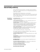
Section 6 Maintenance This section contains instructions for preventive maintenance, diagnostics, general troubleshooting, and corrective maintenance. If the instrument does not function properly, troubleshooting and corrective measures should be taken immediately to circumvent additional problems. PREVENTIVE MAINTENANCE Preventive maintenance consists of cleaning, visual inspection, performance checking, and, if needed, readjustment.
Maintenance detergent and water. Abrasive cleaners should not be used. If the circuit board assemblies must be removed for cleaning, follow the instructions for removal/replacement under the heading of Corrective Maintenance. After cleaning, allow the interior to thoroughly dry before applying power to the instrument. CAUTION. Do not allow water to get inside any enclosed assembly or component.
Maintenance Observe the following precautions to avoid damage: 1. Minimize handling of static-sensitive components. 2. Transport and store static-sensitive components or assemblies in their original containers, on a metal rail, or on conductive foam. Label any package that contains static-sensitive components or assemblies. 3. Discharge the static voltage from your body, by wearing a wrist grounding strap, while handling these components.
Maintenance . SPECTRUM DISPLAY SPAN/DIV READOUT MODE ON OFF L-BAND OFFSET L.O. HIGH >EXIT USE SPAN KEYS TO MOVE CURSOR, PRESS INPUT KEY TO SELECT. MAIN MENU READOUT MODE READOUT POSITION TEST >EXIT USE SPAN KEYS TO MOVE CURSOR, PRESS INPUT KEY TO SELECT. READOUT POSITION OFFSET ADJUST DOWN UP EXIT/SAVE [] [INPUT] UP DOWN LEFT RIGHT EXIT/SAVE [RES] [VIDEO] [] [INPUT] TEST MEMORY DAC LED KEY >EXIT USE SPAN KEYS TO MOVE CURSOR, PRESS INPUT KEY TO SELECT.
Maintenance selected by moving the cursor to a point adjacent to the test name and pushing the INPUT push button. TEST MEMORY >DAC LED KEY EXIT USE SPAN KEYS TO MOVE CURSOR, PRESS INPUT KEY TO SELECT Figure 6-2: 1705A Test menu, displayed when Test is the Main menu selection Memory Test The NOVRAM (Non Volatile Random Access Memory) test is selected from the crt-displayed Test menu by pushing the VIDEO push button.
Maintenance Once communication with the NOVRAM is verified, the microprocessor will attempt to store data. While attempting to store data, the following message is displayed on the crt: READING 2444: DATA STORED AT 60H TO 7F IN PROCESSOR If data cannot be stored in the NOVRAM, the following message will be displayed on the crt: ERROR : CANNOT STORE DATA If data cannot be stored, the probable fault is with either the NOVRAM (U812) or U809 and associated components.
Maintenance ERROR : CANNOT READ OR WRITE TO 2444 PRESS [INPUT] KEY TO EXIT Figure 6-4: 1705A power up error message When this message is displayed, any subsequent measurements (if possible) must be considered suspect. DAC Test The DAC test is used to test the readout capability, crt geometry and focus, and provides a convenient method of determining if Trace Rotation needs to be adjusted. Figure 6-5 shows the waveform superimposed over the crt graticule to demonstrate its value as an adjustment tool.
Maintenance REF Tek - 10 - 20 - 30 - 40 - 50 - 60 - 70 +f L O G Figure 6-5: DAC check waveform used to check Focus, Astigmatism, Geometry, and Trace rotation setting LED and Key Tests There are two additional diagnostic tests that can be made. The LED test alternates high and low levels on the control lines to the front-panel indicators. It can be used to either locate burned-out indicators (visual inspection of flashing indicators) or shorted indicator lines (by probing with an oscilloscope).
Maintenance Refer to the Replaceable Electrical Parts list for a complete description of each component. NOTE. Check the Change Information section at the rear of the manual for corrections and modifications to the instrument and the manual. Look up Charts. Each schematic diagram is assigned an alphanumeric grid and a look up chart which lists the grid location of components on that schematic. Circuit Board Illustrations.
Maintenance The circuit numbers of the individual components in the parts list is made up by combining the assembly number with the individual circuit number. EXAMPLE: R117 on Assembly (circuit board) A3 is listed in the Replaceable Electrical Parts list as A3R117. NOTE. Always consult the parts list and “Change Information” for part numbers and descriptions before ordering replacement parts. Some parts may have been replaced in an individual instrument. Replaceable Mechanical Parts.
Maintenance 3. Determine and evaluate all trouble symptoms. This is accomplished by isolating the problem to a general area such as an assembly. The block diagram is a valuable aid in signal tracing and circuit isolation. CAUTION. Use extreme care when probing with meter leads or probes, because of the high component density and limited access within the instrument. The inadvertent movement of leads or a probe could cause a short circuit or transient voltages capable of destroying components.
Maintenance all obvious defects. In the case of overheated components, determine and correct the cause of overheating before re-applying power. 5. Use successive electrical checks to locate the source of the problem. The primary tool for problem isolation is the oscilloscope. Use the Performance Check Procedure (located in Section 5) to determine if a circuit is operating within specifications.
Maintenance Table 6- 2: Power Supply Fault Symptoms (Cont.) Power Supply cycles OFF/ON Output Check (Low Volts), or High Voltage Oscillator Check (High Volts) Does not power up Control Circuit Check (Low Volts) 5 V not regulating Error Amplifier Check (Low Volts) Improper crt display High Volts Supply Low Volts Supply NOTE. A 20Ω, 2 watt resistor should be used as a load for the Low Volts Supply. Disconnect J4 and connect the 20Ω resistor between W1 (+5 V) and TP1 (secondary ground). 1.
Maintenance CAUTION. Do not proceed until the drain of Q9 is near 0 V. Dangerous voltage potentials are present in the circuit until the capacitors discharge. 2. Rectifier/Switcher Check a. Use the digital multimeter to measure the voltage between TP2 and the tab (drain) of Q9. Be sure the voltage is near 0 V before proceeding. b. Unsolder and lift one end of R102. c.
Maintenance b. Table 6--4 lists the signal present in a properly functioning control circuit. Table 6- 4: Control Circuit Test Points Circuit Location Signal U5, pin 1 Approximately 5 Vdc U5, pin 2 Approximately 2 Vdc U5, pin 3 0V U5, pin 4 80 kHz triangle wave, 2 V p-p U5, pin 6 80 kHz square wave, 18 V p-p U3, pin 1 80 kHz square wave, 5 V p-p U3, pin 2 2.1 Vdc U3, pin 6 2.
Maintenance Table 6- 5: High Volts Supply Fault Symptoms Symptom Procedure Unable to focus crt using the frontpanel control Focus Amplifier Check Unable to adjust crt intensity using the Z--Axis Amplifier Check front-panel control Grid Drive Check No crt display High Voltage Oscillator Check CRT Voltage Check Load the Low Volts Supply with the instrument, or with the 20Ω resistor as stated at the beginning of the Troubleshooting Procedure. Focus Amplifier Check Unsolder and lift one end of R24.
Maintenance Connect the oscilloscope probe to the anode of CR5 and the probe ground to TP1. The signal should be a clipped sine wave of +75 to +200 V p-p. High Voltage Oscillator Check Connect the oscilloscope probe to T1 pin 3 (Q6 collector) and the probe ground to TP1. Power up the supply. The signal should be a +60 V p-p, 22 kHz sine wave. Check the following voltages using the digital multimeter: Table 6- 6: High Voltage Oscillator Test Points Circuit Location Voltage T1, pin 4 Approximately +40 V.
Maintenance CORRECTIVE MAINTENANCE CAUTION. A 2% RMA flux content solder is recommended for making repairs in this instrument. Cleaning of rosin residue is not recommended. Most cleaning solvents tend to reactivate the rosin and spread it under components where it may cause corrosion under humid conditions. The rosin residue, if left alone, does not exhibit these corrosive properties. NOTE. No repair should be attempted during the warranty period.
Maintenance Table 6- 7: Test Selectable Components Circuit Number Nominal Value Range of Values Selection Criteria R50 R74 R73 5.62K 3.40K 18.2K 2.7K to 8.2K 1K to 6.8K 18K to 27K To correct nonlinearities of L--band tuners. R53 115.0K 115K to 130K To alter magnifier range when adjustment range of A3R38 is insufficient. Mechanical Disassembly/Assembly Use these instructions for disassembly and reverse them for reassembly, unless otherwise noted. WARNING.
Maintenance Remove these screws in order to remove the bezel Figure 6-8: Bezel securing screws Graticule Light Removal and Replacement For graticule light removal and replacement, tweezers with curved, serrated tips are recommended. For example: Miltex PL312, 6--100 (equivalent to PL312) or PL317 (longer than PL312). CAUTION. Needle-nosed pliers are not recommended. Replacement bulbs are supplied with this instrument as Standard Accessories.
Maintenance Removal of the CRT 1. Remove the bezel. WARNING. The crt may retain a dangerous charge. Ground the conductor of the anode to discharge the crt. Do not allow the conductor to touch your body or any circuitry. 2. Remove the anode connector and discharge it to ground. 3. Disconnect J2 (trace rotation) on the Main board and push the connector through the hole in the board. 4. The CRT can now be pulled straight out (some pressure is needed).
Maintenance Remove these five (5) screws to remove the rear panel. 333--3990--01 SPECTRUM MONITOR DIE IN DIESEM GERAT ENTSTEHENDE RONTGENSTRAHLUNG IST AUSREICHEND ABGESCHIRMT 20kV BESCHLEUNIGUNGSSPANNUNG KLEINER ALS WARNING TO AVOID ELECTRICAL SHOCK, THE POWER CORD PROTECTIVE GROUNDING CONDUCTOR MUST BE CONNECTED TO EARTH GROUND. 0.
Maintenance TO REMOVE FRONT PANEL ASSEMBLY TO SEPARATE BOARD FROM THE FRONT PANEL TO REMOVE FRONT PANEL ASSEMBLY Figure 6-10: Screws securing the front panel board (A2) in place 3. Remove the board by slipping it through the front--panel opening. 4. To access the Front-Panel board components: a. Remove the knobs from the front. b. Remove the four screws from the rear. c. The board should now separate from the front panel making the components accessible. Removing the L- Band Tuner 1.
Maintenance Remove these screws to remove 70MHZ Turner. J1 FRONT Remove these screws to remove A3 Main bd. Remove this nut to remove L-Band Turner. Figure 6-11: Screws holding the Main board (A3) and the Tuners (A5 and A6) in place 4. Remove the six screws that hold the cover on the 70 MHz tuner. (The cover serves as a hold down for the L--Band tuner.) 5. Slide the tuner back and upward until the L--BAND INPUT connector is clear of the rear panel. Removing the 70 MHz Tuner 1.
Maintenance 2. Remove the plugs from the following connectors: J1 to the Front-Panel board, J4 on the Power Supply board, and J2 on the Main board (Trace Rotation). 3. Unsolder the leads that go to the rear-panel bnc connector and ground the two horizontal crt leads (red and green) and the two vertical crt leads (blue and brown). 4. Slip the crt and trace rotation leads through the appropriate holes in the Main board. 5. Remove the seven screws that are holding the board in place.
Maintenance Ground strap J3 J1 FRONT J2 J4 Remove these screws to remove this board Figure 6-12: Removing the Power Supply board Removing the LNB Power Supply Board 1. Unplug the interconnecting plug from the right side of the LNB power supply. 2. Remove the two Torx screws securing the circuit board to the rear panel. See Figure 6-13. 3. Remove the circuit board. 4. Replace the circuit board by reversing the procedure. Remove these screws to remove LNB Power Supply board (A4) or to replace LNB LED.
Maintenance REPACKAGING If the instrument is to be shipped to a Tektronix Service Center for service or repair, attach a tag to the instrument showing the following information: 1. Owner (with complete address) and the name of the person at your firm that can be contacted. 2. Instrument serial number and a description of the service required. If possible, save and reuse the package in which your instrument was shipped, since this will provide maximum protection. (See Figure 6-14.
Maintenance 3. Cushion the instrument on all sides by tightly packing dunnage or urethane foam between the carton and the instrument. Allow 3 inches on all sides for cushioning. 4. Seal the carton with shipping tape or industrial stapler.
Options
Section 7 Options This section describes instrument options and customer-installable field upgrade kits available for the 1705A Spectrum Monitor. Options CRT Options The standard instrument is shipped with a P31 (green) phosphor crt installed. If Option 74 is ordered, the instrument is shipped with a P4 (white) phosphor crt installed. The crt part numbers are given at the end of the Replaceable Electrical Parts list.
Options Plain Cabinet (1700F00) This plain, silver-grey cabinet is designed for permanent mounting. The ventilating holes in the top, bottom, and sides of the cabinet allow heat generated within the instrument to dissipate. When mounting, allow air to circulate freely through these holes. Carrying Case (1700F02) This silver-grey metal cabinet, designed for portable applications, is equipped with feet, flipstand, and carrying handle.
Replaceable Electrical Parts
Section 8 Replaceable Electrical Parts This section contains a list of the components that are replaceable for the 1705A. Use this list to identify and order replacement parts. There is a separate Replaceable Electrical Parts list for each instrument. Parts Ordering Information Replacement parts are available from or through your local Tektronix, Inc., Field Office or representative.
Replaceable Electrical Parts Column Descriptions Component No. (Column 1) The component circuit number appears on the diagrams and circuit board illustrations, located in the diagrams section. Assembly numbers are also marked on each diagram and circuit board illustration, in the Diagram section and on the mechanical exploded views, in the mechanical parts list. The component number is obtained by adding the assembly number prefix to the circuit number. Example a.
Replaceable Electrical Parts CROSS INDEX - MFR. CODE NUMBER TO MANUFACTURER Mfr. Code. Manufacturer Address 00779 AMP INC 00213 01121 57668 MSD INC.
Replaceable Electrical Parts Mfr. Code.
Replaceable Electrical Parts Component Number Tektronix Part Number A1 A2 A3 A3 A3 A3A1 A4 A5 A6 671-- 4056-- 00 671-- 0041-- 00 672-- 1373-- 05 672-- 1373-- 07 672-- 1373-- 08 671-- 1796-- 01 671-- 0145-- 02 671-- 0042-- 03 119-- 4338-- 00 A10 671-- 3637-- 00 A1 A1C1 A1C2 A1C3 A1C4 A1C5 A1C6 A1C7 A1C8 A1C9 A1C10 A1C11 A1C12 A1C13 A1C14 A1C15 A1C16 A1C17 A1C18 A1C19 671-- 4056-- 00 281-- 0775-- 01 283-- 0021-- 00 283-- 0261-- 00 283-- 0261-- 00 285-- 1341-- 01 281-- 0771-- 00 285-- 1470-- 00 283-- 02
Replaceable Electrical Parts Component Number Tektronix Part Number A1C37 290-- 1267-- 00 A1C38 290-- 1267-- 00 A1C39 A1C40 281-- 0775-- 01 281-- 0772-- 00 A1C41 A1C42 281-- 0563-- 00 290-- 1267-- 00 A1C43 A1C44 A1C45 A1C46 A1C47 A1C48 A1C49 A1C50 A1C51 281-- 0563-- 00 285-- 1331-- 00 281-- 0563-- 00 283-- 0005-- 03 281-- 0563-- 00 281-- 0809-- 00 281-- 0775-- 01 281-- 0563-- 00 281-- 0773-- 00 A1C52 281-- 0773-- 00 A1C53 A1C54 285-- 1437-- 00 290-- 1275-- 00 A1C56 A1C57 A1C58 A1C59 A1C60 A1
Replaceable Electrical Parts Component Number Tektronix Part Number A1CR23 A1CR24 A1CR25 152-- 1165-- 00 152-- 1165-- 00 152-- 0141-- 02 A1CR26 152-- 0141-- 02 A1CR27 A1CR29 A1CR30 152-- 0400-- 00 152-- 0400-- 00 152-- 0141-- 02 A1CR31 A1DS1 A1DS2 A1DS3 A1DS4 A1F1 152-- 0400-- 00 150-- 0050-- 00 150-- 0050-- 00 150-- 0050-- 00 150-- 0050-- 00 159-- 0021-- 00 Effective 200-- 2264-- 00 204-- 0906-- 00 A1J1 A1J2 131-- 5338-- 00 131-- 4794-- 00 A1J3 A1J4 131-- 5337-- 00 131-- 3392-- 00 A1J6 A1L1
Replaceable Electrical Parts Component Number Tektronix Part Number A1Q10 151-- 0350-- 03 A1Q11 151-- 0528-- 00 A1R1 A1R2 A1R3 A1R4 A1R5 A1R7 303-- 0155-- 00 301-- 0225-- 02 303-- 0155-- 00 303-- 0155-- 00 303-- 0155-- 00 322-- 3385-- 00 A1R8 322-- 3097-- 00 A1R11 311-- 1256-- 00 A1R12 A1R13 315-- 0471-- 03 322-- 3097-- 00 A1R14 322-- 3001-- 00 A1R20 A1R22 A1R24 322-- 3248-- 00 322-- 3329-- 00 322-- 3097-- 00 A1R25 322-- 3097-- 00 A1R26 A1R27 A1R28 A1R29 A1R30 A1R31 322-- 3452-- 00 322-
Replaceable Electrical Parts Component Number Tektronix Part Number A1R49 311-- 2239-- 00 A1R50 322-- 3001-- 00 A1R51 A1R52 322-- 3260-- 00 322-- 3001-- 00 A1R53 322-- 3001-- 00 A1R54 A1R55 322-- 3260-- 00 322-- 3322-- 00 A1R56 322-- 3001-- 00 A1R57 322-- 3034-- 00 A1R58 311-- 2239-- 00 A1R59 A1R60 A1R61 322-- 3485-- 07 322-- 3268-- 00 322-- 3034-- 00 A1R62 322-- 3097-- OO A1R63 322-- 3222-- 00 A1R64 322-- 3385-- 00 A1R65 322-- 3385-- 00 A1R66 A1R67 322-- 3452-- 00 322-- 3001--
Replaceable Electrical Parts Component Number Tektronix Part Number A1R86 A1R87 308-- 0793-- 00 322-- 3034-- 00 A1R88 322-- 3222-- 00 A1R89 A1R90 A1R91 A1R92 A1R93 307-- 0746-- 00 305-- 0242-- 00 306-- 0104-- 00 306-- 0104-- 00 322-- 3402-- 00 A1R94 322-- 3402-- 00 A1R95 322-- 3256-- 00 A1R96 A1R97 322-- 3356-- 00 322-- 3222-- 00 A1R98 A1R99 322-- 3289-- 07 311-- 2239-- 00 A1R101 322-- 3068-- 00 A1R102 A1R103 A1T1 A1T2 A1T3 A1TP1 308-- 0290-- 00 322-- 3452-- 00 120-- 1695-- 00 120-- 1945-
Replaceable Electrical Parts Component Number Tektronix Part Number A2DS213 A2DS313 A2DS314 A2P112 A2R211 150-- 1283-- 00 150-- 1289-- 00 ----- ----175-- 9773-- 01 311-- 2540-- 00 Effective 214-- 4725-- 00 366-- 1701-- 01 A2R235 311-- 2287-- 00 366-- 0665-- 00 A2R343 A2R411 322-- 3342-- 00 311-- 2540-- 00 214-- 4725-- 00 366-- 1701-- 01 A2R419 A2R428 311-- 2287-- 00 311-- 2540-- 00 214-- 4725-- 00 366-- 1701-- 01 A2R444 311-- 2540-- 00 214-- 4725-- 00 366-- 1701-- 01 A2R511 311-- 2540-- 00 21
Replaceable Electrical Parts Component Number Tektronix Part Number A2S139 260-- 2300-- 00 Effective 260-- 2300-- 00 366-- 0616-- 00 A2S345 260-- 2300-- 00 366-- 0616-- 00 A3 A3 672-- 1373-- 05 672-- 1373-- 08 131-- 3717-- 00 202-- 0196-- 01 337-- 0607-- 00 337-- 2804-- 00 337-- 3834-- 00 337-- 3923-- 00 337-- 3924-- 00 337-- 3925-- 00 A3C1 A3C2 A3C3 A3C4 A3C5 290-- 0748-- 00 281-- 0819-- 00 281-- 0819-- 00 281-- 0775-- 01 290-- 1296-- 00 A3C6 A3C7 A3C8 A3C10 A3C11 A3C12 A3C13 A3C14 A3C15 A3C16
Replaceable Electrical Parts Component Number Tektronix Part Number A3C33 281-- 0773-- 00 A3C34 281-- 0773-- 00 A3C35 281-- 0773-- 00 A3C36 A3C37 A3C38 A3C39 290-- 0920-- 00 281-- 0775-- 01 281-- 0775-- 01 281-- 0812-- 00 A3C40 A3C41 A3C42 281-- 0775-- 01 281-- 0763-- 00 281-- 0797-- 00 A3C43 A3C46 A3C47 A3C48 A3C49 A3C50 A3C51 281-- 0823-- 00 281-- 0775-- 01 281-- 0775-- 01 281-- 0775-- 01 281-- 0775-- 01 281-- 0538-- 00 281-- 0812-- 00 A3C52 A3C53 A3C54 281-- 0167-- 00 281-- 0775-- 01 281--
Replaceable Electrical Parts Component Number Tektronix Part Number A3C84 281-- 0812-- 00 A3C85 281-- 0812-- 00 A3C87 A3C88 A3C89 A3C90 283-- 0599-- 02 281-- 0809-- 00 281-- 0775-- 01 281-- 0773-- 00 A3C91 A3C92 A3C93 A3C100 290-- 0920-- 00 281-- 0864-- 00 281-- 0765-- 00 281-- 0812-- 00 A3C101 A3C102 A3CR1 281-- 0904-- 00 281-- 0775-- 01 152-- 0141-- 02 A3CR2 152-- 0501-- 01 A3CR3 152-- 0141-- 02 A3CR4 152-- 0141-- 02 A3CR5 152-- 0141-- 02 A3CR6 152-- 0141-- 02 A3CR7 152-- 0141-- 02
Replaceable Electrical Parts Component Number Tektronix Part Number A3CR23 152-- 0141-- 02 A3CR24 152-- 0141-- 02 A3CR25 152-- 0141-- 02 A3CR26 152-- 0141-- 02 A3CR27 152-- 0141-- 02 A3CR28 152-- 0141-- 02 A3CR29 152-- 0141-- 02 A3CR30 152-- 0141-- 02 A3CR31 152-- 0141-- 02 A3CR32 152-- 0141-- 02 A3FL1 A3FL2 A3FL3 A3FL4 A3J1 A3J2 119-- 4325-- 00 119-- 4324-- 00 119-- 2590-- 00 119-- 2590-- 00 131-- 3571-- 00 131-- 4752-- 00 A3J3 131-- 4752-- 00 A3J4 175-- 9797-- 00 A3J5 131-- 29
Replaceable Electrical Parts Component Number Tektronix Part Number A3L6 A3L7 108-- 0987-- 00 120-- 0382-- 00 A3L8 120-- 0382-- 00 A3L9 A3L10 108-- 0826-- 00 120-- 0382-- 00 A3L11 A3L12 A3L14 A3L15 A3L16 A3L17 A3L18 A3L19 A3P3 108-- 0444-- 00 108-- 0444-- 00 108-- 0826-- 00 108-- 0395-- 00 108-- 0262-- 00 108-- 0170-- 01 108-- 0455-- 00 108-- 0395-- 00 131-- 3957-- 00 A3P5 131-- 3957-- 00 A3P6 131-- 3957-- 00 A3P10 131-- 3957-- 00 A3P100 131-- 3957-- 00 A3P101 131-- 3957-- 00 A3P300 131
Replaceable Electrical Parts Component Number Tektronix Part Number A3Q16 151-- 0190-- 00 A3Q17 151-- 0190-- 00 A3Q18 151-- 0190-- 00 A3Q19 151-- 0190-- 00 A3Q20 151-- 0190-- 00 A3Q21 151-- 0188-- 00 A3Q22 151-- 0190-- 00 A3Q23 151-- 0190-- 00 A3Q24 151-- 0190-- 00 A3Q25 151-- 0190-- 00 A3Q26 151-- 0190-- 00 A3Q27 151-- 0347-- 02 A3Q28 151-- 0190-- 00 A3Q29 151-- 0347-- 02 A3Q30 151-- 0190-- 00 A3Q31 151-- 0190-- 00 A3Q32 151-- 0188-- 00 A3Q100 151-- 0188-- 00 A3Q101 1
Replaceable Electrical Parts Component Number Tektronix Part Number A3R13 322-- 3097-- 00 A3R14 322-- 3097-- 00 A3R15 A3R16 322-- 3251-- 00 322-- 3402-- 00 A3R17 A3R18 322-- 3254-- 00 322-- 3402-- 00 A3R19 A3R20 301-- 0181-- 00 322-- 3258-- 00 A3R21 322-- 3097-- 00 A3R23 322-- 3097-- 00 A3R24 322-- 3097-- 00 A3R25 A3R26 322-- 3326-- 00 322-- 3318-- 00 A3R27 311-- 2236-- 00 A3R28 322-- 3318-- 00 A3R29 311-- 2236-- 00 A3R30 322-- 3306-- 00 A3R31 A3R32 322-- 3260-- 00 322-- 3318--
Replaceable Electrical Parts Component Number Tektronix Part Number A3R47 322-- 3318-- 00 A3R48 311-- 2235-- 00 A3R49 311-- 2235-- 00 A3R50 322-- 3265-- 00 A3R52 A3R53 A3R54 322-- 3360-- 00 322-- 3391-- 00 322-- 3318-- 00 A3R55 311-- 2234-- 00 A3R56 311-- 2236-- 00 A3R57 311-- 2234-- 00 A3R58 311-- 2232-- 00 A3R59 322-- 3318-- 00 A3R60 A3R61 322-- 3279-- 00 311-- 2236-- 00 A3R62 322-- 3289-- 00 A3R63 322-- 3289-- 00 A3R64 A3R65 A3R66 322-- 3421-- 00 322-- 3239-- 00 322-- 3346--
Replaceable Electrical Parts Component Number Tektronix Part Number A3R84 322-- 3193-- 00 A3R85 322-- 3258-- 00 A3R86 322-- 3385-- 00 A3R87 322-- 3258-- 00 A3R88 322-- 3193-- 00 A3R89 311-- 2236-- 00 A3R90 A3R91 A3R92 322-- 3246-- 00 322-- 3335-- 00 322-- 3222-- 00 A3R93 A3R94 322-- 3290-- 00 322-- 3226-- 00 A3R95 A3R96 322-- 3277-- 00 322-- 3193-- 00 A3R97 A3R98 A3R100 322-- 3360-- 00 322-- 3260-- 00 322-- 3258-- 00 A3R101 322-- 3258-- 00 A3R102 322-- 3258-- 00 A3R103 322-- 3289-
Replaceable Electrical Parts Component Number Tektronix Part Number A3R124 A3R125 A3R126 A3R127 A3R128 A3R129 A3R131 A3R132 A3R133 322-- 3269-- 02 322-- 3299-- 00 322-- 3481-- 00 322-- 3184-- 00 322-- 3360-- 00 322-- 3260-- 00 322-- 3126-- 00 322-- 3126-- 00 322-- 3369-- 00 A3R134 301-- 0160-- 00 308-- 0344-- 00 A3R135 322-- 3222-- 00 A3R136 322-- 3114-- 00 A3R137 322-- 3130-- 00 A3R138 322-- 3289-- 00 A3R139 A3R140 322-- 3285-- 00 311-- 2238-- 00 A3R141 A3R142 322-- 3143-- 00 322-- 3258--
Replaceable Electrical Parts Component Number Tektronix Part Number A3R162 A3R163 322-- 3284-- 00 322-- 3226-- 00 A3R165 A3R166 A3R167 322-- 3143-- 00 322-- 3024-- 00 322-- 3243-- 00 A3R168 311-- 2234-- 00 A3R169 322-- 3044-- 00 A3R170 A3R171 322-- 3184-- 00 322-- 3097-- 00 A3R172 322-- 3097-- 00 A3R173 A3R174 A3R175 A3R176 322-- 3181-- 00 322-- 3224-- 00 311-- 2227-- 00 311-- 2238-- 00 A3R177 322-- 3222-- 00 A3R178 A3R179 A3R180 308-- 0549-- 00 308-- 0549-- 00 322-- 3289-- 00 A3R181 32
Replaceable Electrical Parts Component Number Tektronix Part Number A3R202 A3R203 A3R204 322-- 3134-- 00 322-- 3134-- 00 322-- 3289-- 00 A3R205 322-- 3281-- 00 A3R206 A3R207 A3R208 A3R209 322-- 3134-- 00 322-- 3134-- 00 322-- 3305-- 00 322-- 3289-- 00 A3R210 322-- 3318-- 00 A3R211 322-- 3097-- 00 A3R212 322-- 3222-- 00 A3R213 322-- 3097-- 00 A3R214 322-- 3258-- 00 A3R215 322-- 3318-- 00 A3R216 322-- 3281-- 00 A3R217 322-- 3235-- 00 A3R218 322-- 3289-- 00 A3R219 322-- 3306-- 00 A3
Replaceable Electrical Parts Component Number Tektronix Part Number A3R239 311-- 2234-- 00 A3R240 311-- 2234-- 00 A3R241 A3R242 322-- 3224-- 00 322-- 3385-- 00 A3R243 A3R244 322-- 3481-- 00 322-- 3289-- 00 A3R245 322-- 3193-- 00 A3R246 322-- 3193-- 00 A3R247 322-- 3097-- 00 A3R300 322-- 3289-- 00 A3R301 A3R302 A3R303 322-- 3315-- 00 322-- 3315-- 00 322-- 3318-- 00 A3R304 A3R305 A3R306 A3R307 322-- 3411-- 00 322-- 3213-- 00 322-- 3313-- 00 322-- 3222-- 00 A3R308 A3R309 322-- 3164-- 00
Replaceable Electrical Parts Component Number Tektronix Part Number A3U15 A3U16 156-- 1451-- 00 156-- 1200-- 00 A3U17 156-- 3972-- 00 A3U18 A3U19 A3U20 156-- 1191-- 00 156-- 1161-- 00 156-- 3972-- 00 A3U21 A3U22 156-- 0515-- 00 156-- 3047-- 00 A3U23 156-- 0153-- 00 A3U24 A3U25 A3U26 A3U27 A3U28 156-- 1191-- 00 119-- 2592-- 00 156-- 1191-- 00 156-- 0742-- 00 119-- 4326-- 00 A3U29 156-- 4200-- 00 A3U30 A3U31 156-- 0515-- 00 156-- 4200-- 00 A3U32 156-- 4199-- 00 A3U33 A3VR1 A3VR2 A3VR3 A3W1
Replaceable Electrical Parts Component Number Tektronix Part Number A3A1DS300 150-- 0168-- 00 136-- 1119-- 01 A3A1J100 131-- 4530-- 00 A3A1P100 131-- 0993-- 00 A3A1P200 131-- 2790-- 00 A3A1P800 131-- 2790-- 00 A4 A4C491 671-- 0145-- 02 290-- 0164-- 00 A4C497 290-- 1311-- 00 A4C580 290-- 1296-- 00 A4C581 A4C583 A4C682 A4C683 281-- 0775-- 01 281-- 0771-- 00 281-- 0775-- 01 281-- 0773-- 00 A4C684 281-- 0773-- 00 A4C690 A4C697 290-- 0747-- 00 290-- 1311-- 00 A4C782 290-- 1311-- 00 A4CR
Replaceable Electrical Parts Component Number Tektronix Part Number A4R581 322-- 3210-- 00 A4R585 322-- 3162-- 00 A4R586 322-- 3289-- 00 A4R587 322-- 3193-- 00 A4R588 322-- 3193-- 00 A4R680 A4R681 322-- 3277-- 00 322-- 3289-- 00 A4R682 A4R685 322-- 3426-- 00 322-- 3306-- 00 A4R686 322-- 3361-- 00 A4R687 A4R688 322-- 3239-- 00 322-- 3193-- 00 A4R690 A4R691 A4R692 A4R693 A4R696 A4U583 308-- 0677-- 00 322-- 3239-- 00 322-- 3239-- 00 322-- 3239-- 00 301-- 0102-- 00 156-- 1799-- 00 A5 671-
Replaceable Electrical Parts Component Number Tektronix Part Number A5C298 A5C299 281-- 0775-- 01 281-- 0772-- 00 A5C389 A5C395 281-- 0811-- 00 281-- 0772-- 00 A5CR280 152-- 1187-- 00 A5E100 A5E101 A5E102 A5E103 A5J400 A5L193 A5L195 A5L197 A5L280 A5L284 A5L389 A5L391 A5L393 A5R181 A5R182 276-- 0569-- 00 276-- 0569-- 00 276-- 0569-- 00 276-- 0569-- 00 131-- 0106-- 02 108-- 0311-- 00 108-- 0734-- 00 108-- 0311-- 00 108-- 0987-- 00 195-- 1805-- 00 108-- 0311-- 00 108-- 0734-- 00 108-- 0311-- 00 322--
Replaceable Electrical Parts Component Number Tektronix Part Number A10SKT1 J890 136-- 1289-- 00 131-- 0372-- 00 Effective 210-- 0224-- 00 S1 260-- 2465-- 00 174-- 2648-- 00 S100 260-- 1780-- 00 210-- 0201-- 00 210-- 0586-- 00 Discontinued Name & Description SOCKET:CRT,TUBE,1730,SAFETY CONTROLLED CONN,RF PLUG: *ATTACHED PARTS* TERM,LUG:0.2 ID,PLAIN,BRS TIN PL *END ATTACHED PARTS* SW,PUSH:0.
Replaceable Electrical Parts 8- 30 1705A Spectrum Monitor
Diagrams/Circuit Board Illustrations
Diagrams/Circuit Board Illustrations Symbols The Replaceable Electrical Parts List is arranged by assembly number in numerical sequence; the components are listed by component number. Example: Graphic symbols and class designation letters are based on ANSI Standard Y32.2--1975. Logic symbology is based on ANSI Y32.14--1973 in terms of positive logic. Logic symbols depict the logic function performed and may differ from the manufacturer’s data.
LOCAL OSCILLATOR 119.8 MHz HELICAL BAND-PASS FILTER 360 MHz 2 TRIPLER 2 BUFFER 3 dB COMBINER 10 kHz RESOLUTION FILTER IF AMP 8 dB 2 2 2 HELICAL BAND-PASS FILTER 130 MHz 3 dB PAD 10.7 MHz 2 2 LOG DETECTOR 2 2 VIDEO FILTER 4 4 V 4 2 nd IF 20 dB 2 300 kHZ RESOLUTION FILTER 4 /10 kHz 130.5 MHz /V FILTER 130.5 MHz X--AXIS 1 70 MHz INPUT VIDEO RESOLUTION LOW-PASS FILTER 1 MICRO PROCESSOR 130.
A3 Main Board Component Locator Comp No Diag Diag No Loc Bd Loc C1 C2 C3 C4 C5 5 5 5 3 5 D1 D1 D1 F5 C3 A4 A4 A4 A4 A5 C6 C7 C8 C9 C10 3 3 5 5 3 F5 B3 G5 G5 F5 B3 C2 C2 C2 C3 C11 C12 C13 C14 C15 3 5 5 3 3 F5 B4 C4 G5 G5 C4 C6 C6 D2 D4 C16 C17 C18 C19 C20 5 5 3 3 3 C3 A5 G5 F5 B3 D6 D2 D3 D3 E6 C21 C22 C23 C24 C25 3 4 4 4 3 D5 C5 C5 D5 H3 F3 G2 G2 G2 G3 C26 C27 C28 C29 C30 4 4 4 3 3 B5 B5 A5 H1 H3 G2 G2 G2 G3 G3 C31 C32 C33 C34 C35 2 2 2 2 2 G1 H1 G1 H1 H1 H2 H2 H3 H3 H4 C36 C3
See parts list for earier values and serial number ranges.
Schematic Diagram <1> Component Locator Chart The schematic diagram has an alphanumeric grid to assist in locating parts within that diagram. Assembly A3 and A5. Partial Assembly A3 also shown on Diagrams, 2, 3, 4, and 5.
+11.8V 12V SHIELD CAN C109 5000PF R398 150.0 70 MHz INPUT VR398 6.2V C298 .1UF C299 4700PF 5 dB PAD (--- 1 dB) --- 25 dBm --- 26 dBm --- 6 dB MIXER REAR PANEL J400 70 MHz INPUT C198 .02UF R299 22.1 L197 150NH R297 22.1 L195 163NH C199 22PF R298 121.0 C194 39PF C196 39PF 3 dB PAD L193 150NH R291 13.0 7 --- 20 dBm 75 OHM --- 32 dBm 5 3 4 C295 4700PF R293 13.0 U190 SBL--- 1 6 3 dB PAD 1 C395 4700PF 8 2 R393 13.0 7 1 C192 22PF 8 --- 35 dBm 2 R391 13.
Schematic Diagram <2> Component Locator Chart The schematic diagram has an alphanumeric grid to assist in locating parts within that diagram. Assembly A3. Partial Assembly A3 also shown on Diagrams 1, 3, 4, and 5.
FL2 VISUAL AID TOP VIEW 11 9 7 TOP VIEW T1 1 +11.8V 6 1 2 5 3 4 4 U25 VISUAL AID TOP VIEW 5 2 4 6 R136 150.0 NOTE: PINS 13--- 16 ARE THE MOUNTING PINS FOR THE PART. 136--- BPF 1 T--- 1907 T1 13 GND 6 14 R201 267.0 2 5 3 4 1 FL2 4 IN C 1 130 MHz IF TUNING 1 1 P5 10.7MHz IF J5 U22 NE5205 C33 .01UF R145 17.4 U25 SBL--- 1 1 2 3 4 1 3 5 C34 .01UF 8 2 1 FL1 VISUAL AID TOP VIEW TEST ONLY C32 4700PF P6 J6 C35 .01UF 7 7 R146 301.0 +11.8VF 3 4 5 6 R141 301.
Schematic Diagram <3> Component Locator Chart The schematic diagram has an alphanumeric grid to assist in locating parts within that diagram. Assembly A3. Partial Assembly A3 also shown on Diagrams 1, 2, 4, and 5.
R158 20.0K 5 R160 511.0K +2V U24B TL072 B3 <5> +5V P101 R126 1.00M --- 2V 7 +40V R243 1.00M J100 1 2 P100 HALF SPAN HALF SPAN H2 6 SWP_SPEED R159 200.0K C49 .1UF <5> W10 0 OHM C40 .1UF <4> +RAMP R97 54.9K R128 54.9K U20C DG444 9 10 14 NOTE: THE NUMBERS BY ADJUSTMENTS ARE FOR THE ORDER OF CALIBRATION. THE NUMBERS MAY NOT MATCH THE SILKSCREEN ON THE BOARD FOR THE 70MHz LINEARITY SECTION. 11 15 --- 11.8V R151 20.0K CR24 U17B DG444 +5V R161 5.23K <5> 7 R143 20.0K R241 2.
Schematic Diagram <4> Component Locator Chart The schematic diagram has an alphanumeric grid to assist in locating parts within that diagram. Assembly A3. Partial Assembly A3 also shown on Diagrams 1, 2, 3, and 5.
+11.8V R139 9.09K R140 50K R152 4.75K VPOSN VERTICAL DEFLECTION AMPLIFIER 2dB GAIN R176 50K 15 KHz LOWPASS FILTER VERT GAIN +5V 1 6 R184 10.0K 12 13 7 R188 6.19K NC 8 7 R209 10.0K 2 H4 --- 11.8V <2> D2 2DB U21C 4053 6 2 R225 1.21K U33 LF351 +SIG BLUE --- SIG BROWN J13 C84 .001UF 4 R224 2.74K U30A 4053 1 6 14 6 13 4 Q27 R223 100.0 1 15 Q26 1 0 R220 511.0 H2 NC 1 NC <5> NC 15 VERT_POSN Q28 R228 7.50K --- 11.8V U21B 4053 B3 <5> R226 35.
Schematic Diagram <5> Component Locator Chart The schematic diagram has an alphanumeric grid to assist in locating parts within that diagram. Assembly A3 and A3A1. Partial Assembly A3 also shown on Diagrams 1, 2, 3, and 4.
8031 ONLY W1 0 OHM AD[0..7] A0 U2 8031 MICROPROCESSOR 31 U8 74ALS573 P0.0 EA/VP C2 33PF P0.1 19 P0.2 X1 P0.3 Y1 12MHZ C3 33PF +5V P0.4 18 X2 P0.5 P0.6 C1 10UF R2 10.0K P0.7 9 1B 2A 2B 3A 3B 4A 4B 5A 5B 6A 6B 7A J1 CONNECTS TO J303 H1 <6> A2 FRONT PANEL BOARD 7B 8A 8B 9A 9B 10A 10B 11A 11B 12A 12B 13A 13B 14A 14B 15A 15B 16A 16B 17A 17B R300 10.
Schematic Diagram <6> Component Locator Chart The schematic diagram has an alphanumeric grid to assist in locating parts within that diagram. Assembly A2 and A4.
+5V +5V 2 2 DS112 VIDEO FILTER ON 1 +5V DS112A 2 VIDEO FILTER DS129 RESOLUTION FILTER 300 KHz 1 RESOLUTION FILTER DS144 INPUT L BAND DS129A J303 1 DS144A S109 S123 FILTER LED_300K LED_ON LED_LBAND +5V +5V 6 6 RESOLUTION FILTER 10 KHz 5 S139 5 LED_10K +5V +5V 2 6 SPAN/DIV 100 KHz 1 DS144C SPAN/DIV 1 MHz 5 LED_100K 3 SPAN_UP 4 1A 1B 2A 2B 5 3A SPAN_DN 6 LED_1M 7 LED_100K 8 LED_FULL 9 LED_10M 10 LED_LBAND 11 LED_70M 12 LED_300K 13 3B 4A 4B LED_70M +5V
A1 Power Supply Board Static Sensitive Devices See Maintenance Section A1 Power Supply Board Component Locator Comp No Diag Diag No Loc Bd Loc Comp No D1 A3 E4 E2 8 8 7 7 7 B1 B1 F2 F2 F3 E3 E3 F1 F2 F3 C47 C48 C49 C50 C51 7 7 7 7 7 C32 C33 C34 C35 C36 7 7 8 7 7 F2 G2 D1 F3 G2 F3 F4 F4 G3 G3 C52 C53 C54 C55 C56 C37 C38 C39 C40 C41 7 7 7 7 7 G3 G2 E4 F4 E4 G4 G4 G4 H4 I4 C42 C43 C44 C45 C46 7 7 7 7 7 D3 C4 D2 D4 C5 I1 J4 I3 I4 I4 Bd Loc Comp No C24 C25 8 8 C27 C28 C29 C30 C31 C1
J5 1 CAUTION: ALL CIRCUITRY TO THE LEFT OF THE ISOLATION BOUNDARY IS AT POWER LINE POTENTIAL AND REQUIRES AN ISOLATION TRANSFORMER TO SERVICE 2 3 3 4 ISOLATION BOUNDARY 5 6 7 8 9 CR10 LINE RECTIFIER AND FILTER C62 NOT INSTALLED C63 NOT INSTALLED L4 1MH CLAMP R102 8 4 USED WITH 1700F10 UPGRADE ONLY 5 6 (DC OPER.) 7 8 9 10 10 11 11 OUTPUT FILTERS MOUNTING C56 .022UF 1 2 L3 4.7UH CR11 +15V R89 5 F1 2A J6 CR23 C44 .
Schematic Diagram <8> Component Locator Chart The schematic diagram has an alphanumeric grid to assist in locating parts within that diagram. Assembly A1. Partial Assembly A1 also shown on Diagram 7.
R61 22.1 HV OSC & ERROR AMP C28 .1UF +100V C19 10UF R66 499K C24 10UF R65 100K 5.5KV P--- P U2 741 P320 1 2 U1 2 IN R59 5.000K +15A +11KV 3 OUT G C27 .1UF +5V 7 C21 .015UF R60 6.04K 2 CRT 1 (g5) 6 CR9 +100V 3 C20 .015UF C65 .47UF 4 GRID DRIVE CR7 R64 100K R50 10.0 R45 100K R63 2.00K R103 499K CR31 GEOMETRY C12 .015UF R48 3.01K CR30 C22 .47UF T1 8 CRT BIAS Q10 C16 10UF 5 Q6 R47 100K C11 .001UF R44 470 ASTIG C17 .
Replaceable Mechanical Parts
Section 10 Replaceable Mechanical Parts This section contains a list of the components that are replaceable for the 1705A. Use this list to identify and order replacement parts. There is a separate Replaceable Mechanical Parts list for each instrument. Parts Ordering Information Replacement parts are available from or through your local Tektronix, Inc., Field Office or representative.
Replaceable Mechanical Parts Column Descriptions Figure & Index No. (Column 1) Items in this section are referenced by figure and index numbers to the illustrations. Tektronix Part No. (Column 2) Indicates part number to be used when ordering replacement part from Tektronix. Serial No. (Column 3 and 4) Qty (Column 5) Name and Description (Column 6) Column three (3) indicates the serial number at which the part was first used. Column four (4) indicates the serial number at which the part was removed.
Replaceable Mechanical Parts CROSS INDEX - MFR. CODE NUMBER TO MANUFACTURER Mfr. Code. Manufacturer Address 17301 RIDGELAND 5825 N TRIPP AVE P.O.
Replaceable Mechanical Parts Fig. & Index No. Tektronix Part No.
Replaceable Mechanical Parts Fig. & Index No. Tektronix Part No.
Replaceable Mechanical Parts Fig. & Index No. Tektronix Part No. Serial Number Effective Dscont 12345 1 CA ASSY,CRT:DISCRETE,ANODE LEAD,CRT,1,22 AWG,30KV,UL3239,58MM DIA A NODE X 1.9 L,0.
47 FIG. 1 EXPLODED VIEW 46 A10 50 44 48 55 45 41 49 40 38 37 36 A4 39 43 51 24 35 A6 30 25 34 42 33 31 28 54 57 A5 29 52 32 53 26 6 7 11 23 12 21 22 4 A1 27 1 60 18 3 20 56 13 2 58 14 59 16 5 10 9 A2 15 8 17 19 A3 A3A1 Test Equipment Depot - 800.517.8431 - 99 Washington Street Melrose, MA 02176 - FAX 781.665.0780 - TestEquipmentDepot.