
Owners manual

5. Locate a suitable grounding point near the
connector such as the vehicle's frame or cross
member. (Do not drill into vehicle floor or bed.)
Clean dirt and rustproofing from area. Drill a
3/32" hole and secure white wire using eyelet
and screw provided.
CAUTION
Verify what is behind any surface prior to drilling to
avoid damage to the vehicle and/or personal injury.
Do not drill into any exposed surfaces.
6. Disconnect the vehicle's Negative (-) battery cable.
If not removed, remove the fuse from the yellow
fuse holder (provided). After cutting the fuse holder
wire, attach the ring terminal and secure to the
vehicle's Positive (+) battery cable. Connect the
other end of the fuse holder to the black 12 ga.
wire, using the yellow butt connector (provided)
f
.
7. Beginning from the front of the vehicle, route the
black 12 ga. wire rearward along the frame rail.
WARNING
Route the wire being careful to avoid any hot
pipes, heat shields, the fuel tank or any other
points that may pinch or break the wire.
8. Continuing on as illustrated, route the black
12 ga. wire to the rear driver's side. Locate the
opening between the vehicle rear bumper and
body allowing entry to the rear driver’s side
taillight area. Route the wire up through this
hole and attach the black 12 ga. wire to the
red wire from the T-Connector black box with
the supplied yellow butt connector
g
.
9. Reconnect the vehicle's Negative (-) battery cable
and install the 10 amp fuse into the fuse holder
from step 6.
WARNING
All connections must be complete for the
T-Connector to function properly. Test and verify
installation with a test light or trailer once installed.
10. Secure all loose wiring. Behind the vehicle
taillight housing assembly on the driver’s side,
clean a flat area using a mixture of rubbing
alcohol and water. Mount the T-connector
black box using double-sided tape provided.
11. Reinstall the taillight housing assemblies,
positioning the vehicle wiring harness between
the housing and the vehicle body. Secure the
remainder of the T-Connector harness with the
cable ties provided, to prevent damage or rattling
and being careful to avoid any areas that would
cut or pinch the wire.
NOTE:
Mount 4-Flat in a suitable location under
the vehicle. Bracket not included.
WARNING
Overloading circuit can cause fires. DO NOT
exceed lower of towing manufacturer rating or:
• Max. stop/turn light: 1 per side (2.1 amps)
• Max. tail lights: (5.6 amps)
Read vehicle's owners manual &
instruction sheet for additional information.
Installation Instructions
Directives de Montage
Instrucciones de Instalación
T-Connector
Connecteur en T
Conector en T
18410-037 Rev. A 12/01/05
ENGLISH
TOOLS REQUIRED:
Drill (3/32" Drill Bit), Philips Head Screwdriver,
Wire Crimpers, Wire Cutters
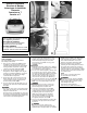
1. Open rear door. Remove both taillight housing
assemblies by removing the three screws for
each light and carefully prying the vehicle taillight
housing assembly away from the vehicle, being
careful not to break the alignment tabs
d
.
2. On the driver’s side, disconnect the vehicle
wiring harness from the taillight socket. Plug the
T-Connector end with the yellow wire in-between
the mating plugs on the driver’s side taillight
socket and vehicle wiring harness.
3. On the driver’s side, route the T-Connector end
with the green wire and the wire with the 4-Flat
connector down through the opening between
the vehicle bumper and body
e
.
4. Route the T-Connector end with green wire to the
passenger’s side and route the 4-Flat underneath
the bumper.
WARNING
Route the wire being careful to avoid any hot pipes,
heat shields, the fuel tank or any other points that
may pinch or break the wire.
Route T-Connector end with
green wire up through
the opening on the passenger side, being careful to
avoid areas that could damage wiring. Repeat step
2 for T-Connector end with the green wire.
READ THIS FIRST:
Read and follow all instructions carefully
before beginning installation.
LISEZ CECI EN PREMIER:
Lire et suivre toutes les instructions
attenrivement avant le montage.
LEA ESTO PRIMERO:
Lea y siga todas las instrucciones cuida-
dosamente antes de iniciar la instalación.
•
d
•
e
•
f
•
g