
Service Manual

© 2015 680_D - 10/15 4 of 48
Preparation
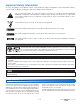
Tools Required
-----------------------------------------------------------------------------------------
• tekmar or jeweller screwdriver
• Phillips head screwdriver
• Needle-nose pliers
• Wire stripper
Materials Required
-------------------------------------------------------------------------------------
• 18 AWG LVT solid wire (low-voltage connections)
• 14 AWG solid wire (line-voltage connections)
• Four 1/8" - 1" wood screws
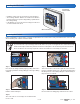
Installation Location
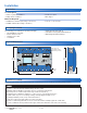
Installation
1 234
Injection
Mixing
Pmp
46 47
N
Snow Melting Control 680
BAS, Boiler & Mixing
37 38
Mod
Boiler
33 34
Stage 1Stage 2
35 36
+
-
BACnet IP
Signal wiring must be
rated at least 300 V
For product literature:
www.tekmarControls.com
Meets Class B: Canadian
ICES & FCC Part 15
tektra 1070-01
Designed and
assembled in Canada
H7021B
Input Power:
115 V (ac) ±10%, 60 Hz, 320 VA
Primary, System Pump Relays:
230 V (ac), 10 A, 1/2 hp
Boiler Stage Relays:
230 V (ac), 5 A
Injection Mixing Pump:
230 V (ac), 2.4 A
Boiler Pump Relay:
230 V (ac), 5 A, 1/3 hp
Floating Action Mixing Output:
230 V (ac), 5 A
BluBrn /
Slab
25
Blk /
Com
26 27 28
Red
19
Brn /
Slab
20
Blk /
Com
Yel
21
Red
24
Blu
22
Yel
23
Snow / Ice Sensor 1 Snow / Ice Sensor 2
Do Not Apply Power
41 42 43
Pwr
Floating
Action Mixing
ClsOpn
Boiler
39 40
Pump
Pump
29 30
Pump
Primary System
31 32
44 45
Power In
NL
BACnet MSTP
Modbus MSTP
16 17 18
Gnd
BA
RS-485
+–
20V
3
dc
5V
dc
Out
0-10V /
4-20mA In Out
Flow
Sensor
Pressure
Sensor
In
Vdc
6
Gnd
7
mA
45
+
Com
8
Boil
Sup
Out
9
Boil
Ret
10
ComCom
11
Sys
Sup
12
Sys
Ret
13 14 15
+
1
Analog
Mixing
2
Temperature Sensors
+––
Disconnect All Power
Before Opening
Use supply wires suitable for at least 105°C
Employer des fils d’alimentation pour au moins 105°C
Do Not Apply Power
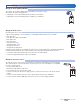
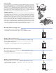
Physical Dimensions
Front View
8–1/16"
(204 mm)
2–15/16"
(74 mm)
Side View
8–1/16"
(204 mm)
11–1/8"
(282 mm)
7/16" (11 mm)
CL
7/16"
(11 mm)
Ø 3/16"
(5 mm)
1/2" Knock-out
(x 16 back) (x 8 top)
(x 8 bottom) (x 2 side)
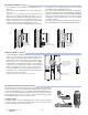
Choose the placement of the control early in the construction process to enable proper wiring during rough-in.
• Keep the control dry. Avoid potential leakage onto the control.
• Maintain relative humidity less than 90% in a non-condensing environment.
• Avoid exposure to extreme temperatures beyond 32-122°F (0-50°C).
• Install away from equipment, appliances, or other sources of electrical interference.
• Install to allow easy access for wiring, viewing, and adjusting the display screen.
• Install approximately 5 feet (1.5 m) off the finished floor.
• Locate the control near pumps and/or zone valves if possible.
• Provide a solid backing which the enclosure can be mounted to. Example: plywood or wall studs.
• Use the conduit knockouts provided on the upper, lower, back and sides of the enclosure for wiring.
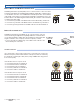
Packaging Contents
The following are included in the product packaging:
• 1 Snow Melting Control 680
• 3 Universal Sensor 082
• 1 Outdoor Sensor 070
• 1 screwdriver
• 1 Application Brochure 680_A
• 1 Installation and Operation Manual 680_D
• 1 BAS Integration Manual 680_B