
Service Manual


13 of 48 © 2015 680_D - 10/15
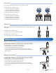
A boiler pump requiring up to 230 V (ac), 5A, 1/3 hp can be switched through
terminals 39 and 40. For simplicity in wiring and troubleshooting, a separate
breaker for each pump is recommended.
• Connect the power source line wire (L) to terminal 39.
• Connect a wire from terminal 40 to the pump L.
• Connect a wire from the pump N back to the power source neutral.
• Connect the ground wire (G) to one of the ground screws provided in the
wiring chamber.
Wiring the Boiler Pump
---------------------------------------------------------------------------------
N
G
L
L
NG
Ground
Pump
39 40
Boiler
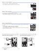
The control provides a floating action signal to operate a floating action actuator. The
floating action mixing output uses dry relay contacts that can switch either 24, 120, or 230
V (ac). When using 24 V (ac), a Transformer 009 is required to power the actuator. The
actuator terminals are typically labelled for clockwise and counterclockwise rotation. The
control's open and close terminals are wired to the actuator depending on the direction
the valve rotates to open and close respectively.
• Connect the power source to the Pwr terminal 43 on the control.
• Connect the Opn terminal 41 to the actuator terminal that rotates the valve open.
• Connect the Cls terminal 42 to the actuator terminal that rotates the valve close.
• If using a 24 V (ac) transformer, connect the actuator common to the transformer C.
• If using a 120 V or 230 V(ac) power supply, connect the actuator common to the
power supply neutral (N).
• If using 120 V or 230 V(ac), connect the ground wire (G) to one of the ground screws
provided in the wiring chamber.
Wiring the Floating Action Mixing Output
---------------------------------------------------------------
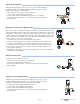
Provide a 15 A circuit for the input power.
• Connect the 115 V (ac) line wire (L) to terminal 44.
• Connect the neutral wire (N) to terminal 45.
•
Connect the ground wire (G) to one of the ground screws provided in the
wiring chamber.
Ground
N
G
L
Power In
L N
44 45
Wiring the Input Power
---------------------------------------------------------------------------------
A variable speed injection mixing pump requiring up to 115 V (ac), 2.4 A is
operated through terminals 46 and 47. For simplicity in wiring and trouble-
shooting, a separate breaker for each pump is recommended.
• Line-voltage is internally supplied through the control.
• Connect a wire from terminal 47 to the pump L.
• Connect a wire from terminal 46 to the pump N.
• Connect the ground wire (G) to one of the ground screws provided in the
wiring chamber.
Wiring the Injection Mixing Pump
----------------------------------------------------------------------
Mixing
Injection
PmpN
46 47
L
NG
Ground
Action Mixing
41 42 43
Floating
Opn Cls Pwr
Com
Close
Open
C
N
L
R