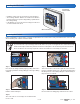
Installation & Operation Manual 680_D Snow Melting Control 680 10/15 Snow Melting Replaces: 04/15 Introduction The Snow Melting Control 680 is designed to operate electric or hydronic equipment to melt snow or ice from any surface including driveways, walkways, business entrances, parking ramps, loading docks, hospital entrances, helipads and car wash bays. It communicates with Building Automation Systems using BACnet ® or Modbus® for alert notification, remote monitoring and adjustment capability.
Table of Contents Important Safety Information..............................................3 Installation..........................................................................4 Preparation..................................................................... 4 Packaging Contents....................................................... 4 Physical Dimensions...................................................... 4 Installation Location........................................................
Important Safety Information It is your responsibility to ensure that this control is safely installed according to all applicable codes and standards. tekmar is not responsible for damages resulting from improper installation and/or maintenance. This is a safety-alert symbol. The safety alert symbol is shown alone or used with a signal word (DANGER, WARNING, or CAUTION), a pictorial and/or a safety message to identify hazards.
Installation Preparation Tools Required-----------------------------------------------------------------------------------------• tekmar or jeweller screwdriver • Phillips head screwdriver • Needle-nose pliers • Wire stripper Materials Required-------------------------------------------------------------------------------------• 18 AWG LVT solid wire (low-voltage connections) • 14 AWG solid wire (line-voltage connections) • Four 1/8" - 1" wood screws Packaging Contents • 1 Application Brochure 680_A • 1
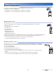
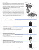
Installing the Enclosure Custom Panel or Electrical Box • Install the control enclosure to a wall or to an electrical box. • Three wiring chamber dividers are included. The dividers provide a barrier to keep low voltage wiring separated from line voltage wiring. • If the dividers are not used, then low voltage circuits must use wire rated at least 300 V.
Rough-In Wiring To prevent the risk of personal injury and/or death, make sure power is not applied to the control until it is fully installed and ready for final testing. All work must be done with power to the circuit being worked on turned off. Please be aware local codes may require this control to be installed or connected by an electrician. • Install the supplied wiring compartment barriers by sliding them into the grooves provided to isolate the low and linevoltage wiring.
Sensor Wiring Wiring the Analog Mixing Output-----------------------------------------------------------------------The control can operate a mixing valve by providing a 0-10 V (dc) or a 4-20 mA signal to the valve actuating motor. • If applicable, connect the mixing actuator positive (+) to terminal 1. • If applicable, connect the mixing actuator negative (-) to terminal 2.
Mounting the Outdoor Sensor--------------------------------------------------------------------------• The temperature sensor (thermistor) is built into the sensor enclosure. • Remove the screw and pull the front cover off the sensor enclosure. • The outdoor sensor can either be mounted directly onto a wall or a 2" x 4" electrical box. When the outdoor sensor is wall mounted, the wiring should enter through the back or bottom of the enclosure.
Immersion Well If a Universal Sensor is mounted onto 1" (25 mm) diameter L type copper pipe, there is approximately an 8 second delay between a sudden change in water temperature and the time the sensor measures the temperature change. This delay increases considerably when mild steel (black iron) pipe is used. In general, it is recommended that a temperature well be used for steel pipe of diameter greater than 1-1/4" (32 mm).
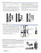
Communication Wiring BACnet MS/TP and Modbus Communication-----------------------------------------------------------A Building Automation System (BAS) can be connected to the control for remote monitoring and adjustment capability. BACnet MS/TP and Modbus communications use an RS-485 connection. Use 18 AWG twisted shielded pair cable. The maximum cable length is dependent on the baud rate and whether terminating resistors are installed.
Snow Sensor-------------------------------------------------------------------------------------------Up to two Snow Sensor 095s can be connected to the control. If the Snow Sensor 1 input is used: • Connect the black wire to terminal 20. • Connect the blue wire to terminal 21. • Connect the yellow wire to terminal 22. • Connect the red wire to terminal 23. Snow Sensor 095 If the Snow Sensor 2 input is used: • Connect the black wire to terminal 20. • Connect the blue wire to terminal 25.
Wiring to a Single-Stage Boiler-------------------------------------------------------------------------A single-stage boiler is enabled through the T-T contacts. • Connect Stage 1 terminals 35 and 36 to the boiler T-T contacts. 33 34 35 36 37 Boiler 1 Stage 1 + Mod - 38 Stage 2 T T Stage 1 Wiring to a Two-Stage Boiler---------------------------------------------------------------------------A two-stage boiler is enabled through the T-T contacts.
Wiring the Boiler Pump---------------------------------------------------------------------------------A boiler pump requiring up to 230 V (ac), 5A, 1/3 hp can be switched through terminals 39 and 40. For simplicity in wiring and troubleshooting, a separate breaker for each pump is recommended. • Connect the power source line wire (L) to terminal 39. • Connect a wire from terminal 40 to the pump L. • Connect a wire from the pump N back to the power source neutral.
Testing the Sensor Wiring A good quality test meter capable of measuring up to 5,000 kΩ (1 kΩ = 1000 Ω) is required to measure the sensor resistance. In addition, the actual temperature must be measured with either a high-quality digital thermometer, or if a thermometer is not available, a second sensor can be placed alongside the one to be tested and the readings compared. First, measure the temperature using the thermometer and then measure the resistance of the sensor at the control.
For the Mix System Output – Analog Mixing • Use an electrical meter set to measure V (dc) or mA. • Set the Mix System Output to 100%. • The voltage between the + and – wiring terminals should be 10 V (dc) or 20 mA. • Set the Mix System Output to 0%. • The voltage between the + and – wiring terminals should be 0 V (dc) or 4 mA. For the Mix System Output – Variable Speed Injection Mixing • Use an electrical meter set to measure V (ac). • Set the Mix System Output to 100%.
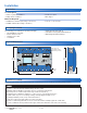
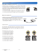
+ – 20V + 5V + – Com Boil Boil Com Sys Sys Com Out + – Gnd Sup Ret Sup Ret 0-10V / dc mA dc Vdc Gnd B A 4-20mA Out In Out In RS-485 9 10 11 12 13 14 15 16 17 18 4 5 6 7 3 8 1 2 Pressure Flow BACnet MSTP Analog Temperature Sensors Sensor Modbus MSTP Mixing Sensor Do Not Apply Power Switch Settings For product literature: www.tekmarControls.
User Interface Home Screen Slab and outdoor conditions information Remaining melting run time System operation information Touchscreen buttons System Operation SYSTEM IS MELTING • Warming Up The slab has not yet reached the slab target temperature. SYSTEM IS OFF • Warm Weather Shut Down The slab and outdoor temperature have exceeded the WWSD setting. • Cold Weather Cut Off The outdoor temperature has fallen below the CWCO setting.
Symbols ! WARNING SYMBOL The control has a error message. Press the warning symbol to determine the error code and information on how to take corrective action. Refer to the Troubleshooting section for a list of error codes. Help Screen The display includes a Help screen for each setting. The Help screen provides a description of the setting that is identical to the description found in the Installation and Operation Manual. Status Menu Navigation Step 1: Press the Status button on the Home Screen.
Slab Status Screen Description Range Access OUTDOOR Current outdoor air temperature as measured by the outdoor sensor or provided by the BAS system. “– – –” is displayed when no outdoor sensor is available. Conditions: Always available. – – –, -67 to 149°F (-55.0 to 65.0°C) User Installer SLAB TARGET The slab target calculated by the control based on outdoor temperature and the melting, idling, or storm setpoints. “- - -” is displayed when no heat is required. Conditions: Always available.
System Status Menu (1 of 2) Description Range Access BOILER TARGET The boiler target calculated by the control based on outdoor temperature, slab temperature and the melting, idling, or storm setpoints. “- - -” is displayed when no heat is required. Conditions: Application mode is set to Boiler or Boiler+Mix. – – –, 50 to 230°F (10.0 to 110.0°C) User Installer BOILER SUPPLY Current boiler supply water temperature. Conditions: Application mode is set to Boiler or Boiler+Mix. -31 to 266°F (-35.
System Status Menu (2 of 2) Description Range Access On or Off User Installer SYSTEM FLOW RATE The system flow rate measured by the flow meter. Conditions: 1) Application mode is set to PWM Zone, Boiler, Mixing or Boiler+Mix and 2) Flow sensor is set to On. 0 to 1000 GPM (0 to 227 m3/h) User Installer SYSTEM PRESSURE The system pressure measured by the pressure sensor. Conditions: Application mode is set to PWM Zone, Boiler, Mixing or Boiler+Mix, and 2) a Pressure Sensor is installed.
Settings Menu Navigation Step 1: Press the Settings button on the Home Screen. Step 2: Press one of the six buttons. Step 3: Press up or down buttons to scroll through the list. Step 4: Press the highlighted setting name to change the setting value. In the BAS menu, settings using a number keypad require touching the number field and then pressing the "Clear" button before entering the number.
Setpoints Menu Description Range Access MELTING SETPOINT Select the desired temperature of the snow melt surface when melting. Conditions: Always available. 32 to 95°F (0.0 to 35.0°C) Default = 36°F (2.0°C) User Installer IDLING SETPOINT Select the desired temperature of the snow melt surface when idling. Idling pre-heats the slab when the slab is dry but cold and allows faster reaction time to reach the melting temperature when snow is detected. Recommended for commercial use only.
Setup – System Setup Menu (1 of 2) Description Range APPLICATION MODE The Application Mode selects the operation of the mechanical equipment. Application Mode “PWM Zone” operates a pump or zone valve to provide heat to the snow melting system. Application Mode “Mixing” operates a mixing valve or a variable speed injection mixing pump to heat the snow melting system. The heat source is enabled. Application Mode “Boiler” operates a modulating, 1-stage or 2-stage boiler to heat the snow melting system.
Setup – System Setup Menu (2 of 2) Description PRESSURE SENSOR Select if a pressure sensor is installed. Conditions: Available when the Application Mode is not set to Electric. Range Access Off or On Default = Off Installer 50, 100, 150, 200, 250, 300 PRESSURE RANGE (345, 690, 1034, Select the maximum pressure rating of the installed pressure sensor. 1379, 1724, 2069 Conditions: Available when 1) The Application Mode is not set to Electric, and 2) Pressure kPa) Sensor is set to On.
Setup – Boiler Setup Menu (1 of 2) Description Range Access BOILER TYPE Select the type of boiler operated by the control. Mod = Modulating boiler with an adjustable firing rate using a 0-10V (dc) or 4-20 mA signal. 1 Stage = Single one-stage on/off boiler. 2 Stage = Single two-stage on/off boiler. EMS = Modulating boiler with an adjustable target temperature using a 0-10V (dc) or 4-20 mA signal. Conditions: Application Mode is set to Boiler or Boiler+Mix.
Setup – Boiler Setup Menu (2 of 2) Description Range Access EMS HIGH TEMPERATURE The EMS modulating boiler target temperature that corresponds to 10 V (dc) or 20 mA. Check the boiler manufacturer’s manual for the maximum EMS target temperature. Conditions: Available when Boiler Type is set to EMS. 50 to 210°F (10.0 to 99.0°C) Default = 210°F (99.0°C) Installer Range Access Setup – Mixing Setup Menu Description MIXING TYPE Select the mixing output type.
BAS Menu (1 of 2) Settings using a number keypad require touching the number field and then pressing the "Clear" button before entering the number. Description Range Access None, BACnet-IP, BACnet-MSTP, Modbus Default = None Installer 0 to 4194302 Default = 1 Installer BACnet-IP PORT Select the BACnet-IP port number. The default BACnet port is 47808 (0xBAC0 in hexadecimal). Conditions: Available when BAS Type is set to BACnet-IP.
BAS Menu (2 of 2) Description Range Access BBMD PORT Set the BACnet Broadcast Management Device (BBMD) UDP port on the BACnet network. Conditions: Available when BAS Type is set to BACnet-IP. 0 to 65535 Default = 47808 Installer BBMD TIME Set the BACnet Broadcast Management Device (BBMD) time-to-live in seconds for foreign device registration on a BACnet network. Conditions: Available when 1) BAS Type is set to BACnet-IP, and 2) Register Foreign Device is set to On.
Monitor Menu (1 of 3) Description Range MELTING ENERGY Records the amount of energy used by the snow melting system since the counter was last reset. Conditions: Always available. Hydronic 0 to 999999 thm or GJ Electric 0 to 999999 kWh Access User Installer MELTING HOURS Records the number of melting hours since the counter was last reset. Conditions: Always available.
Monitor Menu (2 of 3) Description Range Access OUTDOOR HIGH Records the highest measured outdoor air temperature since the counter was last reset. Conditions: Always available. -67 to 149°F (-55.0 to 65.0°C) Installer OUTDOOR LOW Records the lowest measured outdoor air temperature since the counter was last reset. Conditions: Always available. -67 to 149°F (-55.0 to 65.
Monitor Menu (3 of 3) Description Range Access FLOW RATE HIGH Records the highest system flow rate since the counter was last reset. Conditions: Available when 1) Application Mode is not set to Electric and 2) Flow Sensor is set to On. 0 to 1000 GPM (0 to 272 m3/h) Installer FLOW RATE LOW Records the lowest system flow rate since the counter was last reset. Conditions: Available when 1) Application Mode is not set to Electric and 2) Flow Sensor is set to On.
Toolbox Menu Description Range Access ERROR CODE The current error code is displayed. Conditions: Always available. See Error Code Section User Installer ACCESS LEVEL Select the access level of the control. This determines which menus and items are available through the user interface. Conditions: Available when the DIP switch is set to Unlocked. User or Installer Default = Installer User Installer TYPE 680 Product information.
Override Menu Description Range Access MANUAL OVERRIDE Manually override the normal automatic operation of the control to test the equipment or operate the system at the maximum temperature limits. Auto = Normal operation. Auto, Hand, Max Hand = Manual override of each relay output. Heat, Test, Purge, Max Heat = Operate hydronic system at maximum heat. Off Test = Operate electric system for 10 minutes. Purge = Hydronic system purge operates pumps to help bleed air from the system.
Sequence of Operation Snow Melting Overview The snow melting control can operate in one of four different ways: A snow melting system can offer a safe, convenient, and cost effective way of removing snow and ice from the snow melting slab and similar surfaces. Safety is increased by activating the snow melting system as soon as the snow falls rather than waiting for mechanical snow removal after snow has accumulated.
Melt – EconoMelt When a Snow/Ice Sensor 090 or 094 is installed, the installer can choose to select to either automatically or manually start the snow melting system. Selecting EconoMelt to On allows snow removal using a snow plow or shovel. The remaining thin layer of snow or ice that mechanical snow removal methods are unable to remove can be melted using the manual start operation. The snow melting system stops when the sensor is dry. The factory default for EconoMelt is Off.
Tandem Snow/Ice Detection The control allows any combination of two Snow/Ice sensors 090 or 094 or Snow Sensors 095 to be installed. This provides full redundancy and increases the snow detection area. Both sensors are used to detect snow or ice and if either sensor is wet the snow melting zone starts melting. The control continues to operate until both sensors are dry. This allows snow or ice detection over a wider area.
Idle Operation When the snow melting system starts from a cold temperature, there may be a long time delay before the slab is warm enough to melt snow. This time delay allows snow to accumulate on the slab which is not acceptable in some commercial and institutional applications. To decrease the start-up time, the slab can be pre-heated to maintain a minimum temperature. This is known as the Idle temperature.
Slab Protection In a hydronic snow melting system, the boiler or heating plant capacity may be much larger than the load of the snow melting zones. This can result in large temperature differentials between the supply water temperature and the slab creating large tensile stresses on the slab. Concrete is weak to tensile forces and when repeatedly exposed to tensile loads the concrete may crack. This may be prevented by selecting the Slab Protection setting in the System Setup menu to On.
Application Modes The snow melting control can operate either an electric or a hydronic snow melting system. A hydronic system can be categorized as boiler, mixing, boiler and mixing, or pulse width modulation zone operation. A dedicated boiler only provides heat for the snow melting system. A shared boiler provides heat for the snow melting system in addition to the space heating and/or a domestic hot water system.
Boiler Operation 1 Stage Boiler------------------------------------ The control turns the boiler stage 1 relay on or off to fire the boiler and maintain the Boiler Target temperature. The boiler supply temperature operates on a differential that is half above and half below the boiler target. The status of the boiler is shown in the System Status menu.
Mixing Operation • Primary pump — operates continuously during melt, idle or storm • Boiler pump — not used • Boiler stage 1 — turns on when the valve is open or the injection mixing pump is operating.
Troubleshooting It is recommended to complete all wiring to ensure trouble free operation. Should an error occur, simply follow these steps: ! 1. Find: If the control shows the Warning Symbol on the screen, it is indicating a problem on the system. 2. Identify: Press the Warning Symbol to view the error code. 3. Solve: Use the chart below to match the error code to the one on the control. Use the description to solve the problem.
Error Messages (2 of 4) Description SYSTEM SUPPLY SENSOR OPEN CIRCUIT ERROR Due to an open circuit, the control is unable to read the System Supply Sensor 082 on terminals 11 and 12. The control stops operation and does not provide any heat. Check the system supply sensor wire for open circuits according to the sensor installation manual. It may be necessary to replace the system supply sensor. Once the error has been corrected, the error message automatically clears.
Error Messages (3 of 4) Description SNOW SENSOR 1 YELLOW WIRE OPEN CIRCUIT ERROR Due to an open circuit, the control is unable to read the yellow wire connected to the Snow/Ice Sensor 090 or 094, or the Snow Sensor 095 on terminals 20 and 22. The control continues normal operation if snow/ice sensor 2 is installed; otherwise, the control can no longer automatically detect snow or ice, but manual start of the snow melting system is still available.
Error Messages (4 of 4) Description SLAB SENSOR 2 SHORT CIRCUIT ERROR Due to a short circuit, the control is unable to read the Slab Sensor 072 or 073 on terminals 24 and 25. The control continues normal operation if slab sensor 1 is installed; otherwise, Idling and Storm are disabled and energy saving features such as Warm Weather Shut Down (WWSD) and Cold Weather Cut Off (CWCO) are operated using the outdoor temperature only.
Frequently Asked Questions Symptom Look For... Corrective Action Touchscreen is off Power to control Use electrical meter to measure 115 V (ac) voltage on input power L and N terminals. System pump always on Display shows Idle Idle operation requires that the system pump operate continuously while below the melting temperature setting. Blue short Dirt or salt on snow/ The snow/ice sensor requires regular cleaning. Avoid using road salt on the snow ice sensor melting slab.
Technical Data Snow Melting Control 680 BAS, Boiler & Mixing Literature Control Packaged weight Dimensions Display Enclosure Approvals Ambient conditions Power supply Primary, system pump relays Boiler pump relay Boiler stage relays Boiler modulating output Injection mixing pump Floating mixing output Analog mixing output Flow sensor Pressure sensor Communications Sensors –Included –Optional 680_A, 680_B, 680_C, 680_D Microprocessor control. This is not a safety (limit) control. 6.5 lb.