
Submittal Sheet


671
_
C - 08/19 2 of 2 © 2019 tekmar Control Systems Ltd.
Tel: 1-800-438-3903 • F: (250) 984-0815
tekmarControls.com
All specications are subject to change without notice.
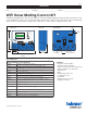
Sample Mechanical diagram
Sample Electrical diagram
This Submittal is not intended to provide full installation instructions and safety information. In order to avoid property
damage or injury, please refer to the complete installation manual and product safety information provided with the product.
Example Application
TT
WiFi Snow Melting Control 671
Pulse Width Modulation
Power
Relays
1084-02
Designed and assembled in Canada
Date Code
H2058A
Blu
3
Yel
4
Brn/
5
Slab
Man
6
Melt
C
7
Blk/
2
Com
Red
1
BoilerHeat
Relay
System
Pump
11 12 13
Do Not Apply Power
Out
10
Com
9
tN4
81
61514
Power
17
L
18
N
For product literature:
Pour la documentation du produit:
Para la literatura del producto:
tekmarControls.com
Disconnect all power before opening.
WARNING
Coupez l'alimentation avant l'ouverture.
ATTENTION
Desconecte la electricidad antes de abrir.
ADVERTENCIA
Signal wiring must be rated at least 300 V.
Le câblage du signal doit être d'une capacité d'au moins 300 V.
Cableado de señal debe tener una
calificación mínima de 300 V.
Contains WiFi transceiver:
FCC ID: Z64-CC3100M0DR1
Meets FCC Part 15B
IC: 4511-CC3100M0DR1
Meets CAN ICES-3 (B)/NMB-3(B)
115 V (ac) ±10%, 60 Hz, 20 VA
230 V (ac) 5 A 1/3 hp
This is a hole
Manual Melt
Time Left
- - : - - hrs
Outdoor
32 °F
Settings Status
System is Melting
Stop
10:30 AM
Warming Up
Brn
Slab
Blk
Com
YelBluRed
Snow
Sensor
095
S4
Legend
B1 = Boiler
BP = Boiler Pump
P1 = System Pump
S1 = Snow/Ice Sensor 090 or 094
S2 = Snow Sensor 095
S3 = Slab Sensor 072 or 073
S4 = Outdoor Sensor 070
B1
S1
S2
S3
S4
671
P1
BP
B1
S1
S2
S3
P1
L
N