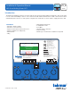
Installation & Operation Manual 671_D WiFi Snow Melting Control 671 08/19 Snow Melting Replaces: New Introduction The WiFi Snow Melting Control 671 operates hydronic and electric heating equipment designed to melt snow and/or ice from roads and walkways surfaces. The control works with tekmar Snow/Ice Sensor 090 or Snow Sensor 095 to automatically detect snow or ice and operates a single boiler, steam valve or electric cable to supply heat to the slab.
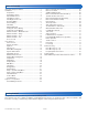
Table of Contents Important Safety Information..............................................3 Installation..........................................................................4 Preparation..................................................................... 4 Packaging Contents....................................................... 4 Physical Dimensions...................................................... 4 Installation Location........................................................
Important Safety Information It is your responsibility to ensure that this control is safely installed according to all applicable codes and standards. tekmar is not responsible for damages resulting from improper installation and/or maintenance. This is a safety-alert symbol. The safety alert symbol is shown alone or used with a signal word (DANGER, WARNING, or CAUTION), a pictorial and/or a safety message to identify hazards.
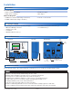
Installation Preparation Tools Required-----------------------------------------------------------------------------------------• tekmar or jeweler screwdriver • Phillips head screwdriver • Needle-nose pliers • Wire stripper Materials Required-------------------------------------------------------------------------------------• 18 AWG LVT solid wire (low-voltage connections) • 14 AWG solid wire (line-voltage connections) • Four 1/8" - 1" wood screws Packaging Contents The following are included in the p
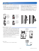
Installing the Enclosure • Install the control enclosure to a wall or to an electrical box. • Three wiring chamber dividers are included. The dividers provide a barrier to keep low voltage wiring separated from line voltage wiring. • If the dividers are not used, then low voltage circuits must use wire rated at least 300 V. Press down at the fingertip grips on top of the front cover and pull out and down. Lift the front cover up and away from the control.
Rough-In Wiring To prevent the risk of personal injury and/or death, make sure power is not applied to the control until it is fully installed and ready for final testing. All work must be done with power to the circuit being worked on turned off. Please be aware local codes may require this control to be installed or connected by an electrician. • Install the supplied wiring compartment barriers by sliding them into the grooves provided to isolate the low and linevoltage wiring.
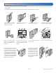
Sensor Wiring Mounting the Outdoor Sensor--------------------------------------------------------------------------• The temperature sensor (thermistor) is built into the sensor enclosure. • The outdoor sensor can either be mounted directly onto a wall and the wiring should enter through the back or bottom of the enclosure. Do not mount the outdoor sensor with the conduit knockout facing upwards because rain could enter the enclosure and damage the sensor.
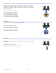
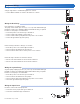
Snow/Ice Sensor---------------------------------------------------------------------------------------A Snow/Ice Sensor 090 or 094 can be connected to the control. The 090 has a 65' (20 m) cable and the 094 has a 208' (63 m) cable. The cable may be extended to a total length of 500' (150 m) using 18 AWG cable. Any junction boxes must kept dry. 1 2 3 4 5 Red Blk/ Blu Yel Brn/ Com Slab If the Snow/Ice Sensor input is used: • Connect the red wire to terminal 1. • Connect the black wire to terminal 2.
tekmarNet The 671 can be connected to other tekmarNet communication compatible controls using the tN4 bus. If tekmarNet is used: • Connect tN4 on the 671 terminal 6 to the tN4 wiring terminal on the other device. • Connect C on the 671 terminal 7 to the C wiring terminal on the other device. • tekmarNet is polarity sensitive. 671 6 7 tN4 C other tN4 control tN4 C 8 9 Manual Melt Input The manual melt input allows the control to be manually switched to melting operation using a switch.
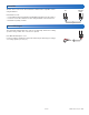
Equipment Wiring Wiring to a Single-Stage Boiler-------------------------------------------------------------------------11 12 A single-stage boiler is enabled through the T-T contacts. • Connect Boiler terminals 11 and 12 to the boiler T-T contacts.
Testing the Sensor Wiring A good quality test meter capable of measuring up to 5,000 kΩ (1 kΩ = 1000 Ω) is required to measure the sensor resistance. In addition, the actual temperature must be measured with either a high-quality digital thermometer, or if a thermometer is not available, a second sensor can be placed alongside the one to be tested and the readings compared. First, measure the temperature using the thermometer and then measure the resistance of the sensor at the control.
Manual Override – Maximum Heat In hydronic application modes, the control includes a Maximum Heat operation where the control operates the snow melting system to maintain the maximum allowed heating setpoints. This allows testing of the snow melting system during warm weather. Step 1: Step 2: Step 3: Step 4: Step 5: Press Settings button. Press Override button. Press Manual Override. Select Manual Override to Max Heat. Press Back button. The control starts the Max Heat operation.
User Interface Home Screen Information about slab and outdoor conditions Remaining melting run time System operation information View status of sensor readings and equipment Go to settings menu to setup control System Operation SYSTEM IS MELTING • The control has either detected snow/ice and automatically started or the control was manually started. • "Warming Up" is shown when the slab is below the slab target temperature.
Symbols ! WARNING SYMBOL The control has a error message. Press the warning symbol to determine the error code and information on how to take corrective action. Refer to the Troubleshooting section for a list of error codes. Help Screen The display includes a Help screen for each setting. The Help screen provides a description of the setting that is identical to the description found in the Installation and Operation Manual. Status Menu Navigation Step 1: Press the Status button on the Home Screen.
System Status Menu Description Range Access MANUAL MELT INPUT When Manual Melt wiring terminal 8 is shorted to common wiring terminal 9, the control is enabled and enters the melting operation unless prevented by warm weather shut down or cold weather cut off. When the manual melt input is disconnected, the control completes the melting cycle and then returns to off, idle or storm operation.
Weather Status Screen When WiFi is turned on, the control receives weather data from the Internet. The current weather, outdoor temperature and forecast snow fall information is displayed. Current outdoor conditions Settings Menu Navigation Step 1: Press the Settings button on the Home Screen. Step 2: Press one of the ten buttons. Step 3: Press up or down buttons to scroll through the list. Step 4: Press the highlighted setting name to change the setting value.
of 36 © 2019 tekmar 671_D - 08/19
Temp Menu Description Range Access 32 to 95°F (0.0 to 35.0°C) Default = 36°F (2.0°C) User Installer IDLING SETPOINT Select the desired temperature of the snow melt surface when idling. Idling preheats the slab when the slab is dry but cold and allows faster reaction time to reach the melting temperature when snow is detected. Recommended for commercial use only. OFF, 20 to 95°F (-6.5 to 35.
Away Menu At Home Select at home to allow automatic snow melting operation. Away Select away to prevent snow melting operation and save energy. The home/away changes devices system-wide. All thermostats and controls that are grouped together on a tekmarNet system will also change together. Display Menu Description TEMPERATURE UNITS Select Fahrenheit or Celsius temperature units. Conditions: Always available. SCREEN BRIGHTNESS Select the screen brightness. Conditions: Always available.
WiFi Menu Before using the WiFi features of this product, you must accept the Terms of Use, as amended from time to time and available at Watts.com/terms-of-use. If you do not accept these terms, this product can still be used without WiFi features.
Energy Menu Amount of time the system has been on in hours per day. Amount of time the system has been on in hours per month. Monitor Menu Description Range Access MELTING HOURS Records the number of melting hours since the counter was last reset. Conditions: Always available. 0 to 999999 hours User Installer HEAT HOURS Records the number of hours the boiler fired or the electric cable heated since the counter was last reset.
Setup – System Setup Menu Description Range Access SNOW/ICE SENSOR Select if a Snow/Ice Sensor 090 or 094 "Inslab", or a Snow Sensor 095 "Aerial" is installed. Conditions: Always available. None, In-slab, Aerial Default = In-slab Installer SLAB SENSOR Select if a Slab Sensor 072 or 073 is installed. Conditions: Available when snow/ice sensor is set to None or Aerial.
tekmarNet Menu Description Range Access ADDRESSING The tekmarNet address of this control. To manually set the address, use the up or down buttons. Auto, x:01 to bus x:24, Installer AUTO ADDRESS The tekmarNet address of this control.
Toolbox Menu Description ERROR CODE The current error code is displayed. Conditions: Always available. Range Access See Error Code Section User Installer ACCESS LEVEL Select the access level of the control. This determines which menus and items are available User or Installer through the user interface. Default = Installer Conditions: Always available.` User Installer TYPE 671 Product information. SW: J1288 1.0.0 SVN: XXX Conditions: Always available.
Sequence of Operation Snow Melting Overview A snow melting system can offer a safe, convenient, and cost effective way of removing snow and ice from the snow melting slab and similar surfaces. Safety is increased by activating the snow melting system as soon as the snow falls rather than waiting for mechanical snow removal after snow has accumulated. This eliminates slip hazards and reduces the risk of injury by mechanized snow melting equipment, thereby reducing potential liability costs.
Melt – EconoMelt When a Snow/Ice Sensor 090 or 094 is installed, the installer can choose to select to either automatically or manually start the snow melting system. Selecting EconoMelt to On allows snow removal using a snow plow or shovel. The remaining thin layer of snow or ice that mechanical snow removal methods are unable to remove can be melted using the manual start operation. The snow melting system stops when the sensor is dry. The factory default for EconoMelt is Off.
Tandem Snow/Ice Detection The 671 can be paired together with a 654 to allow two Snow/ Ice sensors 090 or 094 or Snow Sensors 095 to be installed for a single zone. This provides full redundancy and increases the snow detection area. Both sensors are used to detect snow or ice and if either sensor is wet the snow melting zone starts melting. The control continues to operate until both sensors are dry. This allows snow or ice detection over a wider area.
Idle Operation When the snow melting system starts from a cold temperature, there may be a long time delay before the slab is warm enough to melt snow. This time delay allows snow to accumulate on the slab which is not acceptable in some commercial and institutional applications. To decrease the start-up time, the slab can be pre-heated to maintain a minimum temperature. This is known as the Idle temperature.
Slab Temperature Control the Status menu displays the actual measured temperature, so it is normal to view slab temperatures that exceed the melt, idle, or storm temperature settings. Slab Outdoor Reset Surface temperature = 35ϒF Core (sensor) is warmer Increasing Slab Core Temperature Controlling the slab temperature is critical to minimizing the cost of snow melting. This requires that either a Snow/Ice Sensor 090 or 094 or a Slab Sensor 072 or 073 is installed.
Hydronic Priority Levels--------------------------------------------------------------------------------Priority = None All zones have the same priority and can operate at the same time. This setting is recommended when the boiler plant capacity is sized larger than the heat loss of all zones at design conditions. MELT OFF Zone 1 MELT OFF Priority = Conditional The zone with the lower priority starts melting when the zone with higher priority is warm enough to melt snow or ice.
Warm Weather Shut Down During warm weather, the slab is warm enough to naturally melt snow or ice. The control has a Warm Weather Shut Down (WWSD) setting in the Temperatures menu that prevents the control from entering Melt, Idle or Storm operation in order to conserve energy. The control shows, "System is Off – Warm Weather Shut Down" on the display when WWSD is in effect.
Pulse Width Modulation Zone Operation The control operates the system pump to operate continuously during melt, idle and storm operation. The boiler relays and heat pumps relays operate on a 20-minute pulse width modulation cycle. The relay on time is determined by the calculated slab target and by the measured slab temperature reading. As the slab temperature reaches the slab target, the on time per cycle of the relay is reduced to prevent the slab temperature from overshooting.
Outdoor Sensor An outdoor air temperature is required for proper operation. The control has the option to measure an outdoor air sensor or the outdoor temperature can be provided through the tekmarNet system or through the Internet weather service. This is selected by the Outdoor Sensor setting in the System Setup menu. Exercising The control operates the system pump and heat relay every 3 days to prevent pump and valve seizure.
Error Messages (2 of 3) Description ADDRESS TAKEN ERROR Two devices have been manually set to the same address. The device continues to operate with this error but does not communicate with the tekmarNet system. To clear this error, select an unused tekmarNet address or select automatic addressing. SNOW ZONE TAKEN ERROR Two snow melting controls have been manually set to the same snow zone number. The control continues to operate with this error. To clear this error, select an unused snow zone number.
Frequently Asked Questions Description SNOW/ICE SENSOR ERROR The control is unable to properly detect the Snow/Ice Sensor 090 or 094 on terminals 1, 2, 3, 4 and 5. The control can no longer automatically detect snow or ice, but manual start of the snow melting system is still available. Check the snow/ice sensor brown, yellow, red and black wires according to the sensor installation manual. It is important to check any cable splices for loose wiring connections. It may be necessary to replace the sensor.
Technical Data WiFi Snow Melting Control 671 Pulse Width Modulation Literature Control Packaged weight Dimensions Display Enclosure Approvals Ambient conditions Power supply Relays Manual melt call Communications Sensors –Included –Optional 671_A, 671_C, 671_D, 671_J, 671_U Microprocessor control. This is not a safety (limit) control. 4.3 lb. (1960 g) 6-5/8" H x 7-9/16" W x 2-13/16" D (170 x 193 x 72 mm) 3.